


9
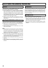
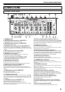
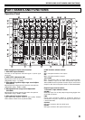
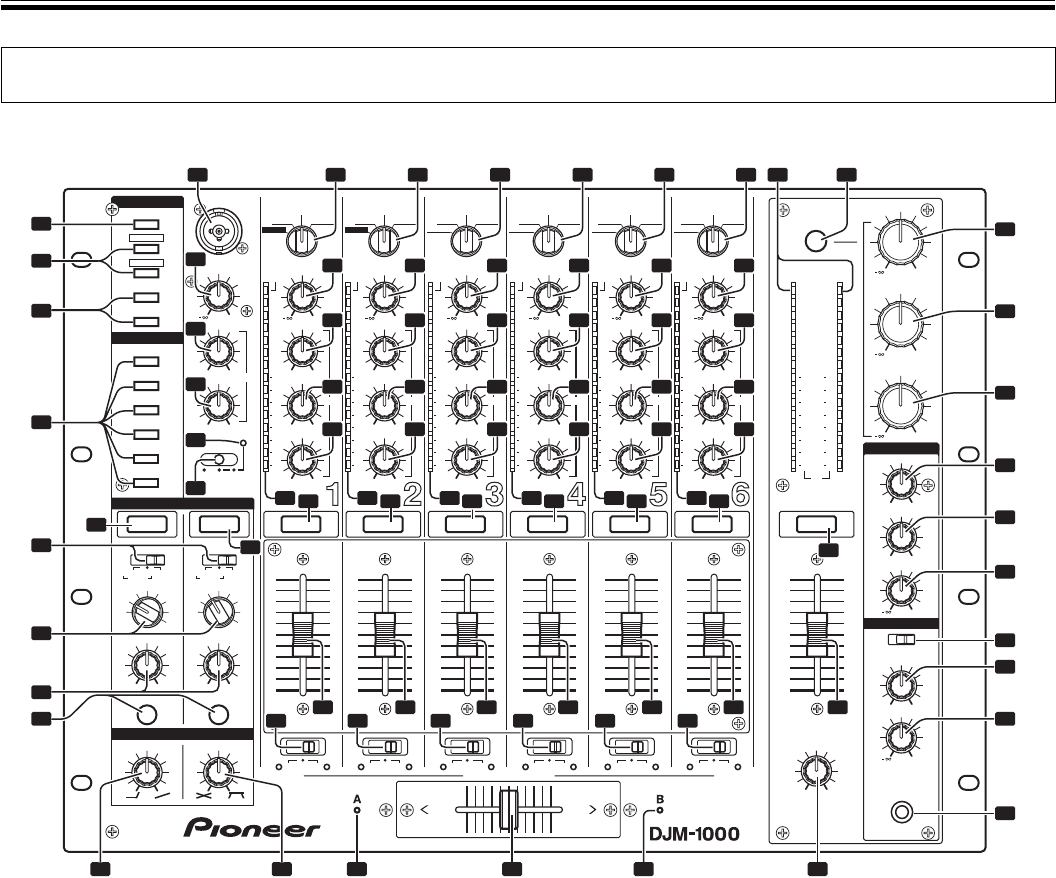
BEFORE USING (PART NAMES AND FUNCTIONS)
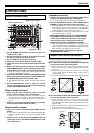
Operation Panel
0
+9
–6+6
–26 +6
–26 +6
–26 +6
A THRU B
–6
OFF
MIN MAX
LEVEL
ON
CH FADER CROSS FADER
CROSS FADER ASSIGN
PROFESSIONAL 6 CHANNEL MIXER
ON
LEVEL
MIN MAX
ON TALK
OVE R
+6
VISUAL
EFX 1
CH-1
CH-2
CH-3
CH-4
CH-5
CH-6
EFX 2
SOUND 1
TRIM
HI
EQ
MID
LOW
LOW
MIC
CUECUE
CUE
HI
MIC LEVEL
MIC
LINK
FADER START
BOOTH MONITOR
HEADPHONES
1 — SEND/RETURN — 2
CURVE ADJUST
V
S 1
S 2
E 1
E 2
1
2
3
4
5
6
10
7
4
2
1
0
1
2
3
5
7
10
15
24
OVER
EQ
10
9
8
7
6
5
4
3
2
1
0
POSTPRE AUX
MIC
MASTER
POSTPRE AU X
+9
CD/LINE
PHONOLINE
–26 +6
–26 +6
–26 +6
A THRU B
TRIM
HI
EQ
MID
LOW
CUE
10
7
4
2
1
0
1
2
3
5
7
10
15
24
OVER
10
9
8
7
6
5
4
3
2
1
0
+9
CD/LINE
PHONOLINE
DIGITAL
–26 +6
–26 +6
–26 +6
A THRU B
TRIM
HI
EQ
MID
LOW
CUE
10
7
4
2
1
0
1
2
3
5
7
10
15
24
OVER
10
9
8
7
6
5
4
3
2
1
0
+9
CD/LINE
PHONOLINE
DIGITAL
–26 +6
–26 +6
–26 +6
A THRU B
TRIM
HI
EQ
MID
LOW
CUE
10
7
4
2
1
0
1
2
3
5
7
10
15
24
OVER
10
9
8
7
6
5
4
3
2
1
0
+9
CD/LINE
PHONOSUBMIC
DIGITAL
–26 +6
–26 +6
–26 +6
A THRU B
TRIM
HI
EQ
MID
LOW
CUE
10
7
4
2
1
0
1
2
3
5
7
10
15
24
OVER
10
9
8
7
6
5
4
3
2
1
0
10
9
8
7
6
5
4
3
2
1
0
+9
+6
CD/LINE
PHONOSUBMIC
DIGITAL
–26 +6
–26 +6
–26 +6
A THRU B
TRIM
0
STEREOMONO
SPLIT
LEVEL
HI
–6 +6
HI
HI
–6 +6
LOW
0
LEVEL
PHONES
CUE MASTER
MIXING
L R
BALANCE
EQ
MID
LOW
CUE CUE
10
7
4
2
1
0
1
2
3
5
7
10
15
24
OVER
10
7
4
2
1
0
1
2
3
5
7
10
15
24
10
7
4
2
1
0
1
2
3
5
7
10
15
24
OVER OVER
10
9
8
7
6
5
4
3
2
1
0
SOUND 2
1
2
3
4
5
6
MIC
MASTER
1
2
3
4
5
6
dBdBdBdBdBdB
dB
+6
MID
+6
LOW
MASTER
L
R
MASTER LEVEL
ISOLATOR
ON
SOUND 2
CD/LINE
PHONOLINE
SOUND 1
INSERT INSERT
1 7
3
4
2
5
6
19 20 22
21
25
8 9 10 11 12 28 29
30
14
13
16
17
18
18
15
14
13
16
17
15
14
13
16
17
15
14
13
16
17
15
14
13
16
17
15
14
13
16
17
15
18181818
18
21 21 21 21 21
24 2723
25 25 25 25 25 26
31
32
33
34
35
36
37
38
39
18
40
47
46
45
44
41
42
43
18
Main microphone input control section
1. Main MIC input connector
Connect to microphones with XLR type or phone type
connector.
2. MIC LEVEL adjustment dial
Adjusts the volume of the main microphone.
(Adjustable range: –∞ to 0 dB)
3. Microphone equalizer high-range sound adjust
dial (EQ HI)
Adjusts the high-range sound of the main microphone.
(Adjustable range: –6 dB to +6 dB)
4. Mic equalizer low-range sound adjust dial
(EQ LOW)
Adjusts the low-range sound of the main microphone.
(Adjustable range: –6 dB to +6 dB)
5. Microphone function indicator
Lights when MIC selector switch is set to [ON]. Flashes
when selector switch is set to [TALK OVER].
6. MIC function selector switch
OFF:
Main microphone audio is not output.
ON:
Main microphone audio is output.
TALK OVER:
Main microphone audio is output. When a sound higher
than –15 dB is input to the main microphone input, the
TALK OVER function operates and the output of all sound
except for the main microphone audio is attenuated 20 dB.
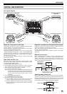
Channel input control section
7. Channel 1 input selector switch
SOUND 1:
Dedicated input for DJ CD players supporting digital link
(mini DIN connector).
LINE:
Phone type connector (When a monaural signal is
connected to only the L channel, the signal is input to both
L and R channels).
CD/LINE:
RCA type connector with line level input.
PHONO:
RCA type connector with phono level input.
PART NAMES AND FUNCTIONS