


4
En
Connections
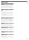
Be sure to turn off the power and unplug the power cord from the power outlet whenever making or changing connections.
Refer to the operating instructions for the component to be connected.
Connect the power cord after all the connections between devices have been completed.
Be sure to use the included power cord.
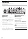
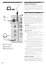
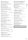
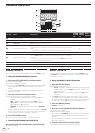
Rear panel
OFF
RETURN
L
1 GND
2 HOT
3 COLD
LR
R
L
R
L
R
L
R
CH 4CH 3
L
R
PHONO
CH 1
CD/LINE
L
R
PHONOCD/LINE
L
RR
LINECD/LINE
L
LINECD/LINE
SIGNAL GNDSIGNAL GND
MASTER1
BOOTH
REC OUTMASTER2
CH2
CONTROL
DIGITAL
MASTER OUT
CH 2
(MONO)
LR
(MONO)
SEND
POWER
AC IN
ON
CH3
1 34646434 552
bc 9f 8e
d7
a
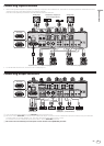
For North America
For Europe
1 POWER button (page 12)
Turns this unit’s power on and off.
2 RETURN terminals (page 5)
Connect to the output terminal of an external effector. When the [L
(MONO)] channel only is connected, the [L (MONO)] channel input
is simultaneously input to the [R] channel.
3 PHONO terminals (page 5)
Connect to a phono level (MM cartridge) output device. Do not input
line level signals.
To connect a device to the [PHONO] terminals, remove the short-
circuit pin plug inserted in the terminals.
Insert this short-circuit pin plug into the [PHONO] terminals when
nothing is connected to them to cut external noise.
4 CD/LINE terminals (page 5)
Connect to a DJ player or a line level output component.
5 SIGNAL GND terminal (page 5)
Connects an analog player’s ground wire here. This helps reduce
noise when the analog player is connected.
6 LINE terminals (page 5)
Connect to a cassette deck or a line level output component.
7 Kensington security slot
8 CONTROL terminal (page 5)
This is a Ø 3.5 mm mini phone jack type DJ player control terminal.
If you connect a Pioneer DJ player using a control cable (supplied
with a DJ player), you can start playback of control other operations
of the DJ player with the fader of this unit.
9 DIGITAL MASTER OUT terminal (page 5)
Outputs the master channel audio signals.
a BOOTH terminals (page 5)
These are output terminals for a booth monitor.
b REC OUT terminals (page 5)
These are output terminals for recording.
c MASTER2 terminals (page 5)
Connect to a power amplifier, etc.
d MASTER1 terminals (page 5)
Connect to a power amplifier, etc.
Be sure to use these as balanced outputs. Be careful not to acci-
dentally insert the power cord of another unit.
e SEND terminals (page 5)
Connect to the input terminal of an external effector. When the [L
(MONO)] channel only is connected, a monaural audio signal is
output.
f AC IN
Connects to a power outlet using the included power cord. Wait until
all connections between the equipment are completed before con-
necting the power cord.
Be sure to use the included power cord.
WARNING
The short-circuit pin plugs out of the reach of children and infants. If
accidentally swallowed, contact a doctor immediately.