


5
Panel Descriptions
fig.0010
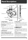
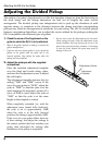
1. Divided Pickup
This pickup detects the vibrations of the
guitar strings. It is attached between the
guitar bridge and the bridge pickup.
2. GK Volume
This controls the volume of the connected
GK device.
* Certain GK-compatible devices also permit the GK
Volume function to be changed. For more detailed
information, refer to the Owner’s Manual for the
GK device being connected.
3. GK Connector
Connect the GK device to this connector.
4. Normal Pickup Input Jack
This jack is for inputting the guitar’s normal
pickup signals to the GK-3. Connect using
the normal guitar cable included with the
GK-3.
5. Select Switch
This switches between the output from the
connected GK device and the normal guitar output.
* Changing the GK Volume function also changes the
function of this switch. For more detailed
information, refer to the Owner’s Manual for the
GK device being connected.
6. DOWN/S1 Switch
7. UP/S2 Switch
The function of the S1 and S2 switches varies
according to the GK device connected. For
more detailed information, refer to the
Owner’s Manual for the GK device being
connected.
8. Power Indicator
This indicates that power is being supplied to
the GK-3. Power to the GK-3 is supplied by
the connected GK device via the GK cable. No
battery or other power source is required.
GK Connector
3.
Select Switch
5.
7.
UP/S2 Switch
6.
DOWN/S1 Switch
1.
Divided Pickup
2.
GK Volume
4.
Normal Pickup Input Jack
8.
Power Indicator
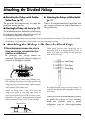
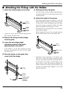
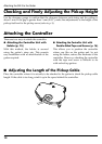
R Adjustment Screw
Yoke
Controller
Pickup
Pickup Cable