


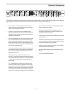

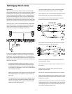
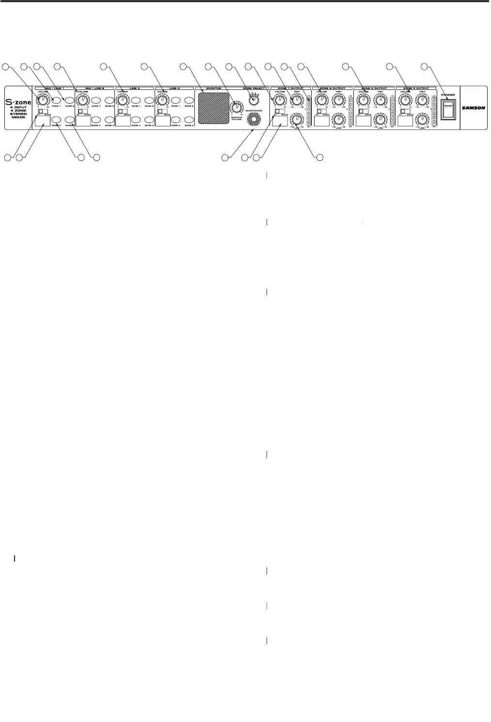
INPUT SECTION
1 VOLUME
– Rotary control used to adjust the level of
signal source connected to channel 1.
2 ZONE 1
– When the LED Backlit switch is pressed
in, the switch lights red and the input is assigned to
ZONE 1.
3 ZONE
2
– When the LED Backlit switch is pressed in,
the switch lights green and the input is assigned to
ZONE 2.
4 STEREO/MONO
switch
- This switch is used to
select either stereo or mono input.
5 SCRIBE STRIP
– Convenient area for marking the
input source allowing you to label the channel with
the device connected to the input.
6 ZONE 3
– When the LED Backlit switch is pressed in,
the switch lights amber and the input is assigned to
ZONE 3.
7 ZONE 4
– When the LED Backlit switch is pressed in,
the switch lights orange and the input is assigned to
ZONE 4.
8 MIC/LINE 2
– Channel 2 input with the same knob
and switch complement as Channel 1.
9 LINE 3
– Channel 3 input with the same knob and
switch complement as Channel 1.
10
LINE 4
10 LINE 410
– Channel 4 input with the same knob and
switch complement as Channel 1.
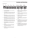
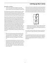
MONITOR SECTION
11 MONITOR SPEAKER
– This built-in, miniature super-
speaker allows you to listen to the signal that is pres-
ent at any ZONE OUTPUT.
12 MONITOR VOLUME
- This rotary control is used
to adjust the monitor level heard in the front panel
Headphone jack or SUPER SPEAKER.
Headphone jack or SUPER SPEAKER.
4
Controls and Functions
Front Panel Layout
13
ZONE SELECT switch
13 ZONE SELECT switch13
– This four-position switch is
used to assign any of the four Zones to play in the
MONITOR SPEAKER or HEADPHONE JACK.
14
HEADPHONE JACK
14 HEADPHONE JACK 14
- Connect any standard stereo
HEADPHONE JACK - Connect any standard stereo HEADPHONE JACK
headphone using a standard 1/4-inch jack to moni-
tor the ZONE OUTPUTS.
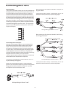
ZONE OUTPUT SECTION
15
VOLUME
15 VOLUME 15
– This rotary control is used to control the
overall level of OUTPUT ZONE 1.
16
HIGH
– High frequency equalizer rotary control
with +/-12 dB of cut or boost at 10kHz.
17
OUTPUT METER
– Six-segment LED meter display-
ing the level of the ZONE 1 OUTPUT with -20 to +14
dB indicators.
18
STEREO/MONO switch
- This switch is used to
select either stereo or mono operation on the ZONE
1 OUTPUT.
19
SCRIBE STRIP
19 SCRIBE STRIP 19
– Convenient area for marking the
ZONE OUTPUT allowing you to notate the room or
area the zone is feeding.
20
LOW
– Low frequency equalizer rotary control with
+/-12 dB of cut or boost at 100Hz.
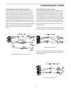
21
ZONE OUTPUT 2
– ZONE 2 OUTPUT with the same
knob and switch complement as ZONE 1 OUTPUT.
22
ZONE OUTPUT 3
22 ZONE OUTPUT 3 22
– ZONE 3 OUTPUT with the same
knob and switch complement as ZONE 1 OUTPUT.
23
ZONE OUTPUT 4
23 ZONE OUTPUT 423
– ZONE 4 OUTPUT with the same
knob and switch complement as ZONE 1 OUTPUT.
24
POWER switch
24 POWER switch 24
– Use this switch to power the unit
on and off.