


5
Controls and Functions
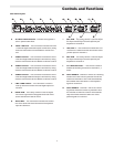
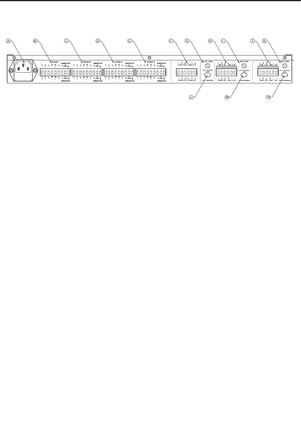
Rear Panel Layout
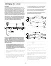
I MIC TRIM
– The rotary control is used to adjust
the input sensitivity of the microphone pre
amplifier on channel 2.
J MIC/LINE 1
– This connector includes the con-
nection for a stereo line level and mono micro-
phone input for channel 1.
K MIC TRIM
– The rotary control is used to adjust
the input sensitivity of the microphone pre
amplifier on channel 2.
L CH 1 MASTER switch
– This switch is used to
enable the ducking function on channels 2, 3
and 4.
M DUCK ENABLE
– Channel 2 will act as a ducking
master when this switch is pressed in and the
volume of channels 3 and 4 will automatically
be lowered when the there is a microphone
signal on Channel 2.
N DUCK ENABLE
– Channel 1 will act as a duck-
ing master when this switch is pressed in and
the volume of channels 3 and 4 will automati-
cally be lowered when the there is a
micro-
phone
signal on Channel 1.
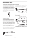
A AC INPUT FUSE HOLDER
– Connect the supplied 3-
pin IEC power cable here.
B ZONE 1 OUTPUT
– This connector includes the Zone
1 Left and Right balanced output connections, along
with the connections for the REMOTE volume con-
trol.
C ZONE 2 OUTPUT
– This connector includes the Zone
2 Left and Right balanced output connections, along
with the connections for the REMOTE volume control.
D ZONE 3 OUTPUT
– This connector includes the Zone
3 Left and Right balanced output connections, along
with the connections for the REMOTE volume control.
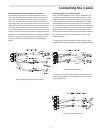
E ZONE 4 OUTPUT
– This connector includes the Zone
4 Left and Right balanced output connections, along
with the connections for the REMOTE volume control.
F LINE 3 AND 4 INPUT
- This connector is used to
hook up the LINE 3 and 4 Left and Right input con-
nections.
G DUCK TRIM
– This rotary control is used to adjust
how much signal level is dropped when the micro-
phone activates the DUCK circuit.
H MIC/LINE 2
– This connector includes the connec-
tion for a stereo line level and mono microphone
input for channel 2.