


If any of the heat-sink-mounted parts (voltage regulators
U1408, U1409 and U1410, or silicon rectifiers D1423 and D1424)
is replaced, be sure to apply a small amount of Wakefield Type
120 Thermal Joint Compound between the component and the
heat sink to allow maximum heat transfer.
A number of components on SHR-14 are mounted on spacing
insulators to keep them a measured distance from the board,
e.g., R1460, D1422. If any of these parts is replaced, be sure to
remount them the required distance above the board on spacing
insulators as originally supplied.
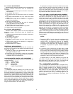
VR1401 POWER AMPLIFIER LIMITER THRESHOLD ADJUSTMENT
This adjustment is made under the following conditions.
1.
Terminate the Speaker Output in a 4-ohm resistive load.
2.
Set the Master control and trimpot VR1401 on SHR-14 fully
clockwise.
3.
Set the Limiter switch to Out.
4.
Connect the unit to a 120 Vac, 60 Hz power source and
switch the unit on.
5.
Drive one low-impedance input channel at 1 kHz with its
channel control fully clockwise. (Turn all the other input
channel Volume Controls fully counterclockwise.) Increase
the input signal until the signal at the Speaker Output just
visibly clips.
6.
Reduce the input signal level such that the output voltage
drops 1.5 dB.
7.
Switch the Limiter In. Slowly turn trimpot VR1401 counter-
clockwise until the output voltage drops an additional 0.2 dB.
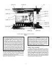
REAR-PANEL BOARDS AND COMPONENTS
The following printed circuit boards and components are
mounted on the rear panel.
SHR-10
INPUT-OUTPUT BOARD
SHR-03 AUX/MIC BOARD
SHR-02
HI-Z INPUT BOARD
SHR-01
LO-Z INPUT BOARD
SHR-13
SPEAKER OUTPUT BOARD
B1
FAN
S3
+24 VDC PHANTOM POWER SWITCH
W1
POWER CORD
J1
AC CONVENIENCE RECEPTACLE
XF1
EXTERNAL FUSEHOLDER
For access to or replacement of any of these parts, turn
the 1200 on its side (power transformer down) and remove the
four Phillips screws that hold the rear panel to the chassis
bottom. The rear panel then can be separated sufficiently from
the chassis bottom to permit access to these boards and
components.
SHR-10 INPUT-OUTPUT BOARD
To remove SHR-10, use a 1/2-in. nutdriver to remove the nuts
on the five phone jacks. Carefully pull the board straight back
until the connectors are free of the rear panel. To separate the
board completely from the rear panel, remove the 6-pin and
4-pin connectors from P1001 and P1002. Unsolder the green
and red leads from the Phantom Power switch, and unsolder
from SHR-10 the yellow lead that connects AC on SHR-10 to
AA on SHR-01. SHR-10 can now be completely separated from
the 1200.
SHR-03 AUX/MIC BOARD
To remove SHR-03, disconnect the four connectors from AA,
AB, BA, and BB to P201 and P202 of SHR-02 and from AC, AD,
BC, and BD to P102 and P104 of SHR-01. Remove the four
Phillips screws that hold the switches to the rear panel; SHR-03
can be completely separated from the 1200.
7
SHR-02 HI-Z INPUT BOARD
To remove SHR-02, remove the six 1/2-inch nuts on the input
jacks. Disconnect the four 3-pin connectors from the SHR-01
LO-Z INPUT BOARD and the two 3-pin connectors from the
SHR-03 AUX/MIC BOARD. Pull the board straight back to
disengage the jacks from the rear panel: SHR-02 can then be
completely separated from the 1200.
SHR-01 LO-Z INPUT BOARD
Remove the twelve screws (two per input) connecting the
XLR-type connectors to the rear panel. To remove SHR-01 without
first removing SHR-02 HI-Z INPUT BOARD, remove the four
Phillips screws that hold the rear panel to the chassis bottom.
Rest the unit on its side while performing this operation. Then
swivel the rear panel away from the chassis (it is still held by the
power cord). This allows SHR-01 to be pulled straight back and
away from the rear panel without being stopped by the interior
vertical metal shield. Disconnect the four 3-pin connectors (two
from SHR-03 and two from SHR-04 CHANNEL BOARDS) and
the four 4-pin connectors (from SHR-02 and SHR-04). (Be sure
to label all removed lead-connector assemblies.) Unsolder from
point AA the yellow lead from SHR-10 REAR PANEL INPUT-
OUTPUT BOARD: SHR-01 is now completely free of the 1200.
SHR-13 SPEAKER OUTPUT BOARD
To remove SHR-13 SPEAKER OUTPUT BOARD:
1.
Disconnect the 3-pin connector from P1301.
2. With a 1/2-inch nutdriver or wrench, remove the nuts holding
the speaker output jacks to the rear panel.
3.
Unsolder the leads from AA and AB.
4.
The SHR-13 board is now free of the 1200.
B1 FAN
To remove the fan:
1.
Remove the four screws, nuts, and starwashers at the four
corners of the fan grille. This frees the fan from the rear
panel.
2. Unsolder the black fan leads from pins AE and AG on SHR-14.
3.
If necessary to remove the fan from the 1200, slide the fan
leads out of the insulating tubing and separate the fan from
the unit.
CAUTION
When replacing the fan, be sure to slide the leads through
the insulating tubing before soldering them to the pins on
SHR-14.
S3 PHANTOM POWER SWITCH
Remove the two screws that fasten the Phantom Power Switch
to the rear panel. This will free the switch from the panel. to
separate the switch completely from the 1200, unsolder the red
and green leads from the switch terminals.
FRONT-PANEL BOARDS AND COMPONENTS
The following printed wiring boards and components are
mounted on the front panel.
SHR-04 CHANNEL BOARD (6)
SHR-05
MASTER CONTROL BOARD
SHR-07 HEADPHONES CONTROL BOARD
SHR-06
HEADPHONES OUTPUT BOARD
SHR-09
LIMITER BOARD
SHR-08
INDICATORS BOARD
S2
POWER ON/OFF SWITCH