


SYMPTOM
PROBABLE CAUSE AND CORRECTION
INPUT OVERLOAD LED flashing
NOTE: Occasional flashing is acceptable
1.
Adjust INPUT ATTENUATION counterclockwise to reduce
channel input level.
2.
Reduce input signal level at source.
Loud clicks when certain microphones or cables are used
1. Make sure PHANTOM 24V switch is not on (when not needed).
2. Make sure unbalanced low-impedance microphone or cable
is not used when PHANTOM switch is on.
3.
Check for defective microphone cables.
No MONITOR output (program output normal)
1.
Make sure channel MONITOR and MONITOR MASTER
controls are turned up.
2.
Make sure controls on external equipment connected to
Monitor output jack are turned up.
3.
Check for defective cable from MONITOR output jack.
Sound quality poor (weak or thin)
1.
Check for excessive treble boost or bass cut on equalization
controls.
2.
Check PROGRAM and MONITOR output jacks for signal
quality (if acceptable, problem is in power amplifier section).
3.
Check for defective cables.
4.
Check impedance match (high- or low-impedance mics)
at input.
SERVICE INSTRUCTIONS
EXTERNAL PARTS
The knobs and feet can be replaced without disassembling
the 1200. All knobs are of the pull-off type, and are color-coded
by function. The Equalization knobs are dual concentric types;
all other knobs are single.
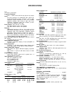
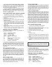
DIAGNOSIS
A simple method of localizing problems without opening the
1200 is as follows. Turn off the Power switch. Do not connect a
speaker or headphone load. Set all controls of the channel
under test only to full clockwise (other channel volume and
monitor controls full counterclockwise), except: Reverb Return
full counterclockwise, and Eq controls centered. Turn the unit
on and apply a 0.5 mV, 1 kHz test signal across pins 2 and 3 of
one of the Bal Lo Z input connectors. Normal voltmeter readings
taken at each output connector are given in Table 1. Similarly, a
5 mV signal inserted in a HI Z input, 50 mV in an AUX input, or
891 mV in the Power Amp and Monitor Inputs will yield similar
output voltages. This method is useful for saving time in localiz-
ing problem areas. Internal servicing should be performed only
by qualified service personnel.
WARNING
Voltages in this equipment are hazardous to life. Refer
servicing to qualified service personnel.
Normal Blow type.
EXTERNAL FUSE REPLACEMENT
To replace line fuse F1 (with no apparent problems in the
Powermixer), disconnect the line cord from the ac source and
remove the rear panel fuseholder cap by pushing it in and
turning it counterclockwise (either a screwdriver or fingertip
may be used.) Replace the defective fuse only with a 5A 250V
TABLE 1. NOMINAL TEST VOLTAGES
CAUTION
If trouble symptoms (overheating, erratic operation, etc.)
were apparent before the fuse blew, or if the replacement
fuse blows, a qualified service person should trouble-
shoot the Powermixer carefully to find the source of the
problem. Do not continue to replace fuses; have the
trouble corrected.
OUTPUTS
INPUT
Input
Spkr Prgm Mix
Mon Phones
Tape
LO z 0.5 mV 28 V
890 mV
1.78 V
6.31 V
178 mV
HI Z
5 mV 22 V 708 mV
1.41 V
5.01 V 141 mV
AUX
50 mV
28 V 890 mV 1.78 V 6.31 V
178 mV
PA
891 mV 25 V
--- ---
5.62 V
---
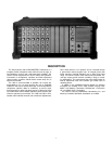
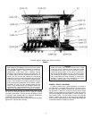
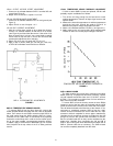
SERVICE ACCESS
Disconnect the 1200 from its power source. To open the unit
for servicing, remove ten screws and lockwashers from the top
and five from each side of the cover. The cover can then be
lifted off exposing the internal parts (see Figure 1).
3