


SHR-04 CHANNEL BOARD
SHR-09 LIMITER BOARD
The SHR-04 Channel Boards are assembled and installed in
To free SHR-09 LIMITER BOARD from the Mounting Panel,
pairs. Therefore, SHR-04s for Channel 1 and Channel 2 constitute
remove from the front of the panel the two Phillips screws that
one pair, those for Channel 3 and Channel 4 constitute another
attach the Limiter Switch to the panel. This frees the board from
pair, etc. To remove any pair of Channel Boards:
the panel.
1.
Remove the control knobs by pulling them off the shafts.
2.
Remove the two flat-head Phillips screws that hold the Channel
Board Assembly in place. One screw is attached to the top of
the front panel ledge, the other to the chassis bottom.
3.
Disconnect the Channel Bus Connector from the top of each
of the two Channel Boards.
4.
Disconnect the 3-pin connector (coming from SHR-01 Input
Board) from the bottom of each of the two SHR-04 Channel
Boards.
5.
Pull the Channel Board Assembly horizontally backward to
free the control shafts from the front panel; the Assembly is
now free of the 1200.
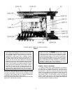
FRONT MOUNTING PANEL
The Front Mounting Panel must be freed from the Front Panel
in order to work on or remove SHR-05 MASTER CONTROL
BOARD, SHR-06 HEADPHONES INPUT BOARD, SHR-07
HEADPHONES CONTROL BOARD, SHR-09 LIMITER BOARD,
SHR-08 INDICATORS BOARD and the Power On/Off Switch
from the 1200. To remove the Mounting Panel:
1.
2.
3.
4.
5.
6.
7.
8.
9.
Remove the two flat-head Phillips screws from the front
panel ledge above the Mounting Panel.
Rest the 1200 on its side with the fan and mounting panel
upwards.
Remove the top three Phillips screws holding the front panel
to the chassis bottom. Leave the bottom screw (below Channel
1) in place. (This will permit swiveling the front panel far
enough away from the chassis to allow the Mounting Panel
to be freed from the 1200 after other required disconnections
have been made.)
Remove the knobs from the control shafts of the Master and
Headphones Controls.
Disconnect the 3-pin connector from P701 on the HEAD-
PHONES CONTROL BOARD.
Disconnect the 3-pin connector from P601 on the HEAD-
PHONES OUTPUT BOARD.
Disconnect the CHANNEL BUS connector from P501 at the
top of the MASTER CONTROL BOARD and disconnect 8-,
4-, and 5-pin connectors from P502, P503, and P504 at the
bottom of the MASTER CONTROL BOARD.
IMPORTANT:
Mark all connectors before removing them so
that they can be reconnected correctly.
Loosen the cable tie that holds the cable harness to the hole
in the outside bottom of SHR-05.
Swivel the front panel away from the chassis bottom enough
to permit pulling the control shafts out of the front panel and
partially freeing the Mounting Panel from the 1200. (The
panel is still connected to the 1200 by the transformer leads
connected to the On/Off switch.) From this position it is
possible to remove or work on boards SHR-05, -06, -07,
-08, and -09.
SHR-05 MASTER CONTROL BOARD
To remove SHR-05 MASTER CONTROL BOARD from the
Mounting Panel:
1.
Remove the control knobs.
2.
Use a nutdriver or wrench to remove the nuts holding the
control shafts to the Mounting Panel.
3. To free the board, pull the shafts back out of the panel.
SHR-06 HEADPHONES OUTPUT BOARD AND SHR-07 HEAD-
PHONES CONTROL BOARD
SHR-06 and SHR-07 are connected together by a soldered-
in-place 4-conductor ribbon cable. If it is not necessary to
replace the cable, either remove both boards (if desired to free
one of them completely from the 1200), or only remove one (if
freeing the assembly from the 1200 is not essential).
To remove SHR-07 HEADPHONES CONTROL BOARD, remove
the 7/16-inch nut that holds the control shaft to the Mounting
Panel. This permits the board to be freed from the panel (although
it is still connected via the ribbon cable to SHR-06 HEADPHONES
OUTPUT BOARD).
To remove SHR-06 HEADPHONES OUTPUT BOARD, remove
the 1/2-inch nut that holds the phone jack to the Mounting
Panel. This permits the board to be freed from the Panel.
SHR-08 INDICATORS BOARD
Remove the two Phillips screws holding SHR-08 to the back
of the Mounting Panel. Pull the board back from the panel to
remove the LEDs from their holes and to free the board.
S2 ON/OFF SWITCH
To remove the On/Off Switch from the Mounting Panel:
1.
Pull the switch button off the switch control shaft.
2.
Remove the two Phillips screws that hold the switch to the
panel.
3.
Unsolder the red and black transformer leads from the switch.
A1200MX INPUT EXPANSION MODULE
The A1200MX is an optional input expansion module kit that
provides two additional input channels to the 1200. A maximum
of two A1200MXs can be added to the 1200 for a total of 10
inputs. The A1200MX consists of an input connector module
(SHR-15 and SHR-16), an input transformer module (SHR-17),
a channel control module (two SHR-04s), control knobs, and
hardware.
The A1200MX circuitry is identical to the input circuitry of the
other six input channels. Servicing can be accomplished in the
same manner. Printed wiring board drawings are provided with
the service drawings.
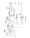
CHECKING ACTIVE COMPONENTS
Integrated circuits can be checked without removing them
from their circuit board. Measure the input, output and power
supply voltages as shown on the applicable circuit diagram.
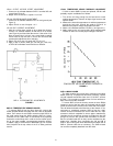
Defective transistors and diodes can be located by use of a
standard ohmmeter such as a Simpson 260. Polarity of the
ohmmeter must be verified before these checks are made; all
resistance measurements are made with the power off in the
circuit under test.
With a known diode orientation, measure the diode resistance
in the forward and reverse directions. The lowest meter reading
will establish the probe at the cathode end (schematic symbol
arrow points to cathode) as the “minus” probe while the other
probe will be “plus.” (Some ohmmeters are not polarized in this
manner with relation to “volts plus probe” and “volts minus
probe.“) With the ohmmeter “plus” probe on the anode end of a
diode, and the “minus” probe on the cathode end, the ohmmeter
should be read approximately 2000 ohms or less. With the
meter probes reversed, a reading of about 10,000 ohms or
more should be obtained. If either of these conditions is not
met, one lead should be unsoldered from the circuit and the test
repeated. If the results are identical, the diode should be replaced.
8