


2
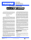
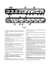
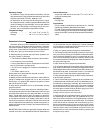
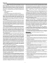
MODEL FP410
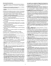
FIGURE 1
1
2
3
4
5
6
7
8
9
10
111
2
3
4
5
6
7
8
9
10
111
2
3
4
5
6
7
8
9
10
11
432
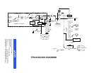
LINK
FP410
TAPEOUT
MIC LINE MIC LINE MIC LINE MIC LINE MIC LINE MIC LINEPHANTOM
OFF ON
OUT IN
MASTER
PULLFOR1KHZTONE
BATTERYTEST MANUALAUDIO LIMITERIN
PULLFORMONITOR
OFF ON
PEAK
VU
100%
MONITORIN
4321
PHONES
1
1
2
3
4
5
6
7
8
9
10
11
1
2
3
4
5
6
7
8
9
10
11
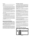
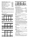
--20 --10 --7 --5 --3 --2 --1 0 +1 +2 +3
--24 --20 --16 --12 --8 --4 0 +4 +8 +12 +16
Selectable Off--Attenuation control for seamless operation
Automatic gain adjustment as additional microphones are
activated
Defeatable“LastMicLock--On”circuitkeepsatleastonemi-
crophoneonatalltimes—maintainsacousticambianceand
prevents confusing background sound changes
Wide, flat frequency response and low distortion up +18
dBm output
Linking capability for systems containing over 25 mixers
and over 100 microphones
LED indication of microphone channel mix levels, output
level, and limiter action
Automatic muting prevents annoying thumps and loud-
speaker damage when unit is turned on and off
Transformer-- balanced inputs and outputs switchable to
line-- or microphone--level
Separate monitor input and tape output (aux--level) jacks
Front--panel headphone monitor jacks with level control
Front--panel auto-- disable switch for manual operation
Operates from ac mains voltage or two 9 V batteries
Switchable14 V and 48V phantompowering forcondenser
microphones
Underwriters Laboratories Listed and Canadian Standards
Association listed as Certified (FP410 only)
CONTROLS, CONNECTORS, INDICATORS
(See Figure 1)
1. MicrophoneChannel Gain Controls1--4: At“0” position, mi-
crophone channel is removed from operation. Turning control
clockwise activates microphone channel and allows adjust-
ment of microphone level.
2.Input NormalGreenLED: Shouldflickerwith normalspeech
levels.
3. Input High Red LED: Should flicker only on loud speech
peaks.
4. Flat (
)/Low--Cut ( ) Slide Switches: Provide low--fre-
quency rolloff to reduce undesirable low-- frequency s ignals
such as wind noise.
5. MASTER Rotary Control: Determines the level of the com-
bined input signals at Mic/Line, Tape and Phones outputs.
PULL FOR 1 kHz TONE position activates 1 kHz tone oscilla-
tor(tonelevelisdeterminedbyMastercontrolsetting).Oscilla-
tor signal appears at all outputs.When oscillator is not in use,
knob should be pushed in.
6.PEAK/VU OutputLevel Meter:Meter functionis selectedby
adjacent PEAK/VU slide switch. In PEAK switch position, me-
ter indicates peak signal levels. In VU position,it indicates av-
erage signal levels, simulating a true VU meter.
7.BATTERYTESTMomentarySlide Switch:Operates incon-
junction with PEAK/VU Meter to indicate battery condi-
tion.With POWER switch on and switch in momentary--on po-
sition, new set of batteries lights all green LEDs. Number of
green LEDs lit indicates approximate battery life remaining
whenalkaline batteriesareused.NOTE:POWERLEDbegins
flashingwhentotalbatterysupplyvoltagedropsto10Vdc(one
green LED lit).
8.MANUAL/AUTOSlideSwitch: Selectsmanualorautomatic
microphone operating mode. In MANUAL position, unit oper-
ates as a conventional microphone mixer. In AUTO position,
unused microphones automatically turn off.