


3
9. LIMITER IN Slide Switch: Activates fast--acting, peak--res-
ponding limiter circuit to cut overload distortion during loud
program intervals without affecting normal program levels.
The red limiter LED indicates limiting action.
10. PHONES
1
/
4
--inchand 3.5mmPhone Jacks: Permitmoni-
toringmixeroutput throughmoststereoor monoheadphones.
PULL FOR MONITOR switch applies signal from rear --panel
MON IN 3.5 mm phone jack to headphones amplifier. When
switch is activated, mixer output signal does not appear in
headphones output. PHONES rotary control determines
headphone level in either case.
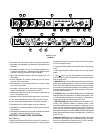
11. POWERSlide Switch:Applies acor battery power tomixer
circuitry. Adjacentgreen LED indicates power--on status and,
in battery operation, flashes when total battery voltage drops
to 10 Vdc.
12. 100--120 VAC, 50/60 Hz 8W 3--Pin Power Connector: For
connectionto 100to120Vac, 50/60Hzpoweroutlets (230Vac
in the FP410E).
13. OUTPUT 3--Pin Male XLR Connectors: For connection to
one ortwo amplifiers, recordersor other mixers. Outputsignal
levels are individually switchable to Line level or low--impe-
dance Mic level by adjacent individual MIC/LINE slide
switches. Both jacks provide the same signal information but
are electrically isolated.
14. TAPE OUT 3.5 mm Phone Jack: Provides output signalto
feed unbalanced aux--level inputs of most tape recorders and
amplifiers.
15. LINK IN/OUT 8--Pin miniature DIN Jacks: Using link
cables,thesejackspermitvirtuallyunlimitednumberof FP410
mixers to be stacked to achieve additional input capacity.
Jacks carry audio signals, MaxBus and Last Mic Lock--On in-
formation.
16. MON IN 3.5mm Phone Jack:Sends external Aux or Line--
levelsourcetoheadphonesamplifierwithoutinterruptingother
mixer functions. Jack is activatedby pulling front--panel PULL
FOR MONITOR knob outward.
17. PHANTOM ON/OFF Slide Switch: Controls application of
14 Vdc phantom power for condenser microphones to all i n-
puts.With switchonand INPUTMIC/LINEswitchesin MICpo-
sition,+14Vdcisappliedtopins2and3ofeachinputXLRcon-
nector. NOTE: Phantom power can be internally set to 48 Vdc
(see Modifiable Functions section). When using other than
Shure condensermicrophones,verify thatvoltage andsource
resistance requirements are compatible (see Specifications).
18. INPUT 1--4 Female 3--Pin XLR Connectors: Permit con-
nection to balanced, low--impedance microphones or line--le-
velsources.AdjacentMIC/LINEslideswitchesadjustinputsto
match source levels.
19. Battery Compartment: Accepts two 9--volt batteries for re-
moteoperation oras automaticbackup inthe event ofac pow-
er failure.
INSTALLATION AND OPERATION
Mixer Installation
Install the FP410 as follows. If the unit is to be placed on a
horizontalsurface,attachthefoursuppliedbumperstothecor-
ners of the chassis bottom to prevent marring the surface.
If the FP410 is to be rack--mounted in a standard 483 mm
(19--inch) audioequipment rack,remove thetwoPhillips head
screws from each FP410 side panel, place the rack “ears” in
position at the sides (rack--mount holes facing forward), and
secure the ears with the previously removed Phillips head
screws. NOTE: The rackears are asymmetrical;the widerear
should be on your right (as you face the front panel) to permit
access to the battery compartment while the FP410 is in the
audio equipment rack. Install the rack--mounted FP410 in the
equipment rack and secure it with the four supplied rack --
mount screws.
Make electrical connections as follows.
1. For battery operation, compress the release latches of the
battery drawer with thumb and forefinger, and withdraw the
drawer from the compartment. Observing battery polarity
markings, insert two fresh 9--volt batteries in the drawer
slots.WiththePowerswitchon,slidetheBatteryTestswitch
to the right to determine battery condition. IMPORTANT:
Battery operating life is reduced when microphones are
phantom --powered—especially by 48 Vdc phantompower-
ing.Foracoperation,connectthepowercordtoa100to120
Vac,50/60Hzsource(FP410E:Connecttoa230Vac,50/60
Hz source).
2. Connect the microphones and/or line--level signal sources
to the Mic Input connectors (use conventional 2--conductor
shielded cables). Adjust Mic/Line switches as required for
incoming signal level.
3. If phantom--powered condenser microphones are used,
turn on the FP410’s Phantom Power switch. NOTE: With
condenser microphones other than Shure, verify that volt-
age and source resistance requirements are compatible.
4. Connect one or both of the FP410 Outputs to the following
mixers, amplifiers or recorders. Make certain each Output
Mic/Line switch is in the proper position for the desired out-
put levels.
5. If an unbalanced aux--level output is needed, connect it to
the Tape Out jack.
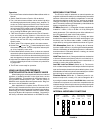
6. If additional FP410 mixers are to be linked to increase the
number of microphone inputs, connect them by means of
the Link Inand LinkOut jacks.Connect the LINKOUTof the
first mixerto the LINKIN ofthe nextmixer, andso on.Leave
the LINK IN jack of the first mixer and the LINK OUT jack of
the last mixer unconnected. NOTE: Jacks are for linking
only, not for audio inputs or outputs.
7. If headphone monitoring of the FP410 mixed signal is re-
quired, connect mono or stereo headphones to one of the
front--panel Phone jacks (
1
/
4
--inch or 3.5 mm). Adjust the
Phone control knob for the desired loudness (after s etting
the microphone Channel and Master Gain controls accord-
ing to Operation section).
8. To monitor an external signal source,connect it to the rear--
panelMonInjackandpullthePhonescontrolknoboutward.
Adjust the Phones control and/or the external source level
control for the desired loudness.