


4
Operation
1. Turn on thePowerswitch andset the Manual/Auto switchto
Manual.
2. Set the Peak/VU meter to Peak or VU as desired.
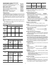
3. The 1 kHz internal tone oscillator can be used to help align
the following equipment levels (master mixer, amplifier, re -
corder, etc.)to the output level of the FP410.The toneoscil -
lator is activatedby pulling the Master gaincontrol outward.
Its level at the FP410 output is set by the Master gain con-
trol. After setting equipment levels, turn off the tone oscilla-
tor by pushing the Master gain control inward.
4. “Talk” the microphone connected to the FP410 Channel 1
input, and slowly raise the Channel 1 Gain control to the
point where the green LED flickers regularly with normal
speech, and the red LED only occasionally with louder
speech peaks.
5. Set the other FP410 channel gains in the same manner.
6. Set the Flat (
)/Low--Cut ( ) switchesadjacent to each
Gaincontrolasrequired.Thelow--cutpositionreducespick-
up of low--frequency room noise.
7. Set the Manual/Auto switch to Auto. In about one second,
unused microphone inputswill turnoffand thelevel of anin-
dividual talker’s voice will rise above the background noise
and reverberation to become clearer and more intelligible.
8. Adjustthe FP410Master Gain controlfor the desiredoutput
level, asindicated bythe Peakor VUmeter,or bythe follow-
ing equipment.
9. The FP410 is now ready for operation.
USING AN EQUALIZER/FEEDBACK
CONTROLLER WITH AN AUTOMATIC MIXER
When setting up a sound system which has an outboard
equalizer or feedback controller in the signal chain, set the
FP410 to MANUAL. This activates all microphone inputs, so
every possible feedback path is open. With the FP410 in
MANUAL mode, equalizethe sound systemand/or “RingOut”
the room to set the feedback controller.
After equalization is complete, set the FP410 to AUTO-
MATIC mode. Remember thatthe input of anautomatic mixer
dropsby 3dBevery timethe numberactivated inputsdoubles.
When using an FP410 in MANUAL mode, the master output
drops by 9 dB when all 8 inputs are activated. Conversely, it
will rise by 9 dB when switched back to AUTOMATIC mode.
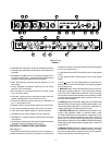
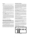
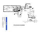
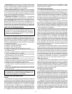
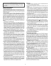
MODIFI ABLE FUNCTION S
The FP410 is ready for automatic or manual operation as
supplied.Additionalversatilityisprovidedby easilyaccessible
switches visible when the battery compartment is removed.
Note that the s witches are all in the “up” position as supplied;
changes are made by moving the switch or switches down-
ward. The switch positions are illustrated by a label belowthe
battery compartment (see Figure 2).
VU Meter(Switch No.1). Changethe VUmeter,suppliedcal-
ibrated for +4 dBm = 0 VU, to +8 dBm = 0 VU by moving this
switch downward. (This switch does not affect calibration of
the LED output level meter in the Peak position.)
Limiter Threshold (Switch Nos. 2, 3). Change the limiter
threshold, the output level at which limiter action begins, from
the factory--set +16 dBm to either +8 dBm, +4 dBm or 0 dBm
output level by moving these switches as shown in Figure 2.
Off--Attenuation (Switch No. 4). Change the off-- attenua-
tion from13dB toinfinite (
)by moving thisswitch downward.
Withthe13dBsetting,anunusedmicrophoneis13dBlowerin
level than when it is activated. With the
setting, an unused
microphone is completely off.
Hold Time(SwitchNo.5). Changetheholdtime,theduration
of time an activated microphone (which is not locked on) re-
mainson after thetalker stops talking,from 0.4seconds to 1.0
second by moving this switch downward.
Last Mic Lock--on Defeat (Switch No. 6). The last mic
lock--onfeaturekeepsthemostrecentlyactivatedmicrophone
open until anewly activated microphonetakes its place. Itcan
bedefeatedsothat allmicrophonesautomaticallyturnoffafter
the hold time by moving this s witch downward.
Phantom Power (Switch No. 7). Phantom power for con-
denser microphones, normally 14 V, can be changed to 48 V
by moving thisswitch downward.CAUTION: Makecertainthe
condenser microphones to be used are compatible with the
selectedvoltage.Ifthemicrophonescanoperate properlywith
14 Vphantompower,that positionshould beused to avoidex -
cessive battery drain.
INTERNAL MODIFI ABLE FUNCTIONS
∞
METER
0VU
LIMITER
THRESHOLD
OFF-
ATTEN
LAST MIC
LOCK-ON
PHANTOM
POWER
+4
+16
13 dB IN0.4 SEC +14 V
+8 OUT1.0 SEC +48 V
+8
+4
0
HOLD
TIME
MODIFIABLE FUNCTION SWITCHES
FIGURE 2