


5
WARNING
Voltagesin thisequipment arehazardous tolife. Nous-
er--serviceable parts inside.Refer allservicing to quali-
fied service personnel.
In addition to the user--modifiable functions described
above,the FP410isdesigned sothatmanyofits functionscan
be modified by a qualified technician. Instructions on imple-
menting these modifications are provided in the FP410 Ser -
vice Manual which is obtainable from Shure. These modifica-
tions are:
1. Change Monitor In sensitivity.
2. Change Tape Out level.
3. Change Off--Attenuation value.
4. Change low--cut filter frequency.
5. Change Peak meter attack and decay time constants.
6. Change 0 VU Meter calibration to level other than +4 or +8
dBm.
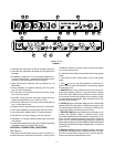
7.ChangeLimiterthresholdbeyondthepositions permittedby
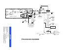
Switches 2 and 3 (see Figure 2).
8. Change to permanently lock one or more microphones on.
9. Change to permanently prevent one or more microphone
channels from activating.
10. Change the preset Hold Time values.
11. Change the Monitor In jack to an Aux In jack function for
cascading mixers or creating a “mix--minus”.
12. Change to provide reduced--level program feed in head -
phones when Pull For Monitor switch is activated.
13.TheFP410canbechangedtooperatefrom230Vac,50/60
Hz power.Similarly, theFP410E canbe changedto operate
from 100 to 120 Vac, 50/60 Hz mains voltage.
WARNING
The safety certifications of the FP410 and FP410E do not
apply when the operating voltage is changed from the
factory setting.
ADDITIONAL INFORM ATION
Limiter
Thefront--panelLimiter switchturns onafast --acting,peak--
responding limiter circuit that cuts overload distortion during
loud program intervals without affecting normal program lev-
els. When theswitch is In (operating), the FP410output is lim-
ited to approximately +16 dBm. Increasing the individual or
Master gain controls will increase the average output and the
amount of limiting. The limiter threshold can be changed from
its factory setting as described in the Modifiable Functions
section. The front--panel red LED adjacent to the Limiter
switch indicates limiter action.
Linked Mixers
The FP410 provides four microphone inputs. If additional
mic inputs are needed, more FP410s (over 25, if necessary)
can be “linked” using link cables of the type supplied. A setup
like this can provide over 100 mic inputs. As long as the link
jacks of all mixers are connected (out--to--in, sequentially,
leaving one Link In and one Link Out jack unconnected), the
automatic mixing functions will be shared by all units.
When FP410 mixers are linked, Shure Intellimix control
functions are also linked so that a single multi--microphone
system is created. All input signals (except the Monitor In sig-
nal) appear at all linked mixer outputs. There is no master/
slave relationship.
The output--related controls and functions of each linked
mixer are post--link and do not affect the signals appearing at
other linked mixer outputs. Each mixer’s output controls may
besetdifferentlytoobtaindifferentresults.Thesecontrolsare:
Master level control, 1 kHz Tone Oscillator, Peak/VU Meter
switch,Limiter Inand Limiter Threshold switches,Phone level
and Monitor control, and Off --Attenuation switch. NOTE: The
actual off--attenuation in the 13 dB switch position increases,
as more mixers are linked. This reduces excessive noise and
reverberationcontributedby theincreasednumberoftypically
“off” microphones.
The input--channel--related controls and functions of each
linkedmixerarepre--linkanddonotaffecttheinputchannelsof
other linked mixers. The effect of these input controls is re-
flected in the mixed output signals of all the linked mixer out-
puts. These controls are: Input channel levels controls and
Low--Cut switches, Manual/Auto switch, Phantom On/Off
switch, Phantom Voltage Selector switch, Hold Time switch,
and Last Mic Lock-- On switch.
Link Cables
Additional link cables can either be purchased (Shure Part
No. 95A1143; 305 mm—12 in.) or constructed using desired
lengths of high--quality, 7--conductor, s hielded cable (pin 1:
shield)with8--pinminiDINconnectorson eachend.Themaxi-
mum length of a link cable will depend on the grounding con-
siderations of this unbalanced line.
FP410 and Mixing Consoles
The FP410 can be used in conjunction with large mixing
consolestoprovideautomaticmixingfortalkshows,paneldis-
cussions,andnightlynewsshows.Largeconsoleshavechan-
nel insert jacksso that externalsignal processing devicescan
be patched into individual channel signal paths. These jacks
are normally line level.
The FP410 can be fed from these insert jacks and the
FP410 output then fed to a submaster fader on the console.
This arrangement allows the operator complete control of
eachchannel viatheconsole’sinputcontrol strip,whilethethe
FP410 keeps thenumber ofopen microphones toa minimum,
relieving the operator of having to open and close mic chan-
nels.
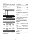
SUPPLIED ACCESSORIES AND REPLACEMENT
PARTS
Battery Tray Assembly 90GJ2600.....................
Bumper (Foot) Kit (4 in kit)) 90S8100..................
Control PC Board Assembly 90B8368A................
Knob, Master & Phones 95A8238.....................
Knob, Channel Gain 95B8238........................
Line (Power) Cord (FP410) 95A8231..................
Line (Power) Cord (FP410E) 95A8247.................
Link Cable 95A1143.................................
Left Rack--Mount Bracket 53A8252....................
Right Rack--Mount Bracket 53A8253..................