


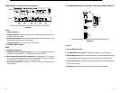
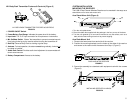
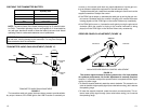

LX88-II Receiver Features & Controls (Figure 1)
LX88-II DUAL CHANNEL RECEIVER FEATURES & CONTROLS
FIGURE 1
FRONT
BACK
2
5
7
6 98
3
4
1
2 3
4
1
7 6
Front
1. Power Indicators.
2.
RF Signal Indicators. Yellow indicates when RF (radio frequency) signals are re-
ceived from the transmitter.
3. Audio Peak Indicators. This light flickers occasionally in normal operation; is ON
steadily when the audio input is overloaded.
4. Volume Controllers. Controls the audio output level.
5. POWER ON/OFF Switch.
Back
6. Antenna Connectors.
7.
Independent Audio Output Connectors. There is a separate balanced XLR
connector and unbalanced
1
/
4
–inch phone jack for each channel.
8. Mixed Channels Audio Output Connector. An unbalanced,
1
/
4
–inch phone
jack
connector mixes both channels into a single output. This comes in handy
when the mixer or amplifier has only one audio input.
9.
Power Input Connector. Connects to a PS20 (120 Vac) or PS20E (230 Vac)
power adapter.
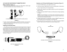
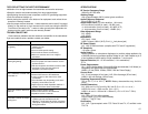
LX2 Handheld Microphone-Transmitter Features & Controls (Figure 2)
LX2 MICROPHONE–TRANSMITTER FEATURES & CONTROLS
FIGURE 2
1
5
BAT
MUTE
2
3
4
LX2
6
1. Grille.
2. Power ON/OFF Switch.
3. Power/Battery Fuel Gauge. Indicates the power level of the battery.
4. Mic On/Mute Switch. “Mutes” the transmitter to prevent unwanted sounds
from being picked up by the receiver
without
turning the transmitter off.
5. Audio Gain Control. Provides audio level adjustment to accommodate dif-
ferent sound sources.
6. Battery Cover. Access to the battery and the audio gain control.
2
3