


SETTING GAIN LEVELS
With the system in place and connected, all units can
now be turned on and the levels set to their optimum
positions.
TRANSMITTER
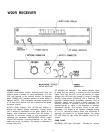
Place the POWER Switch of the W20R receiver in the
ON position. The green POWER LED will light.
Turn the transmitter POWER ON/OFF Switch on.
Observe the receiver yellow RF SIGNAL LED. It should
be continually lit, indicating adequate RF signal
strength for good transmission. If the LED continually
flickers or does not light, consult the Troubleshooting
section of this manual.
Turn the transmitter MIC ON/OFF Switch to the ON
position. With a microphone connected to the transmit-
ter, the receiver AUDIO LEVEL display will now respond
to varying sound levels.
Set the transmitter GAIN Switch as dictated by the
type of input: Hi for low-impedance microphones; LO
for high-impedance microphones and instrument
pickups.
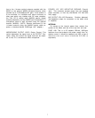
Sound Pressure Levels
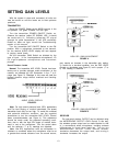
Normal. The transmitter MIC LEVEL Control has been
factory-set to provide optimum audio modulation at the
receiver, as indicated by LED illumination in the -7 to 0
range (see Figure 3). Readings in this area will yield the
highest dynamic range without overload and resulting
distortion.
AUDIO LEVEL DISPLAY
FIGURE 3
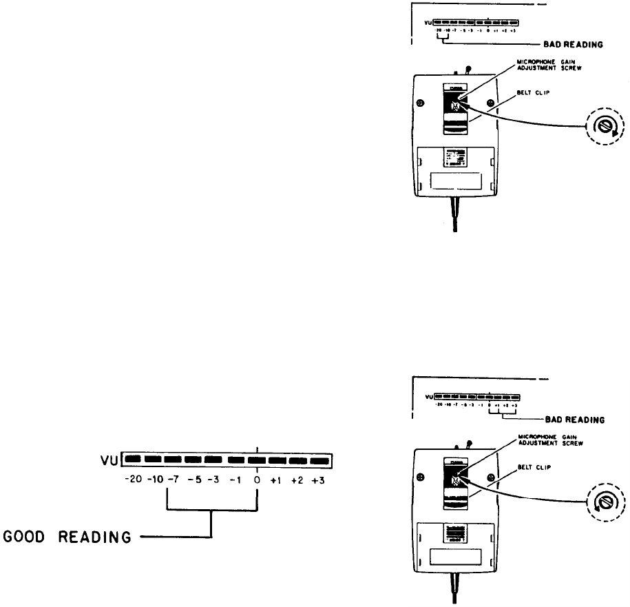
High. For high sound pressure level (SPL) applications
such as loud singing or musical instruments, the preset
transmitter level may be too high. To avoid this overload
and potential distortion condition, use the supplied
screwdriver to turn the transmitter MIC LEVEL Control
down (counterclockwise; see Figure 4). This adjustment
should be made under the expected operating condi-
tions, that is, with the high SPL singer or musical instru-
ment in use at the microphone. Turn the control down
until the optimum (-7 to 0) readings are obtained.
Low. Low SPL applications such as soft-spoken in-
dividuals or conditions where the microphone must be at
a greater-than-normal distance from the sound source,
HIGH SPL GAIN ADJUSTMENT
FIGURE 4
may require an increase in the transmitter gain setting.
To correct for a low-level condition, turn the MIC LEVEL
Control up (clockwise; see Figure 5) until a proper (-7 to
0) LED reading is obtained.
LOW SPL GAIN ADJUSTMENT
FIGURE 5
RECEIVER
The rear-panel receiver OUTPUT can be adjusted using
the MICROPHONE OUTPUT LEVEL Control. In this way,
the wireless system output can be made identical to that
of a conventional wired microphone, avoiding extreme
differences in input level settings. Turning the
MICROPHONE OUTPUT LEVEL Control counter-
clockwise decreases the output level, and turning it
clockwise increases the output.
10