


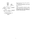
W20R RECEIVER
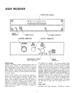
FRONT PANEL
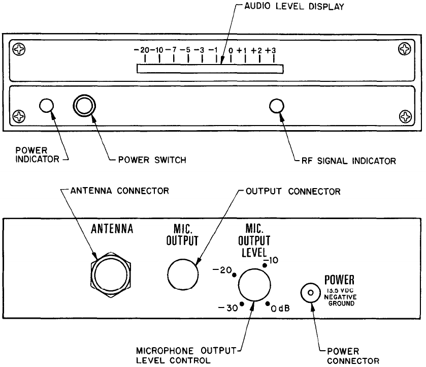
POWER Push-Button Switch: Applies power from the
external power converter or other well-filtered 13.5 Vdc
(200 mA) sources to the receiver circuitry. An adjacent
green POWER LED Indicator remains on while power is
applied. (NOTE:
With the power converter connected to
a 115 Vac, 60 Hz source, 13.5 Vdc is present at the power
converter output.)
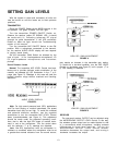
AUDIO LEVEL Display: This IO-LED bar display in-
dicates the relative system modulation. Normal opera-
tion is shown by illumination of the green portion of the
display, with occasional excursions into the yellow. If
frequent or constant yellow or red indications are
observed, the transmitter MICROPHONE LEVEL control
should be lowered (counterclockwise), or the Gain
switch set to the Lo position. The display is calibrated in
volume units (VU).
RF SIGNAL LED Indicator: This yellow indicator lights
to show that the receiver is picking up the transmitted
signal. Note that the LED is not an indicator of signal
strength (the LED will light through a range of marginal
through strong signal conditions), but a flickering LED
generally indicates barely acceptable operation, and no
indication means that no signal is being received. The
receiver contains a squelch circuit to eliminate un-
wanted signals or noise in the absence of wireless
transmitter signals. The squelch circuit is not user-
adjustable; it is preset to an optimum threshold setting
of 1.0 µV, minimizing setting errors and difficulties in
returning the squelch to its original setting. The yellow
RF LED does not light when the squelch circuit is ac-
tivated.
REAR PANEL
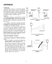
ANTENNA UHF-Type Connector: Provides for connec-
6