


ANTENNAS
TRANSMITTER
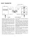
The transmitter antenna is a permanently attached,
flexible wire, 1/4-wave antenna. It has an omnidirectional
transmission pattern (equally effective in all directions)
and is designed to operate in a vertically polarized mode.
This means that the antenna should hang downward dur-
ing operation; coiling or wadding it to minimize visibility
will reduce the system’s operating distance.
RECEIVER
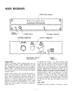
The receiver antenna is a single-section, 1/4-wave
whip antenna approximately 457 mm (18 in.) in length.
Like the transmitter antenna, the receiver antenna has
an omnidirectional pickup pattern and are vertically
polarized. Vertical mounting is a requirement for op-
timum pickup.
For “problem”
installations, improved performance
may be obtained using an optional 5/8-wave whip anten-
na (WA250). Up to 3 dB gain increase can be realized with
this antenna over the standard 1/4-wave.
Also available for use with the 5/8-wave antenna are a
7.6m (25 ft) coaxial cable (WA280) for remotely locating
the antenna (necessary where the receiver is to be
mounted in a shielded rack mount enclosure or other
poor RF location), and a wall-mount bracket (WA260) for
affixing the antenna to a variety of surfaces. The
5/8-wave antenna can also be mounted on a conven-
tional microphone stand using a microphone swivel
adapter such a the Shure A25B or A25C.
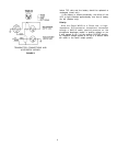
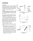
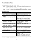
RECEIVER-TRANSMITTER DISTANCE
Observing the following rules regarding transmitter to
receiver antenna distance will yield the best results
possible.
Keep the transmitter to receiver antenna distance as
short as possible. As the distance increases, the
transmitted signal is weaker (see Figure 6).
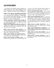
Make certain the signal path between the transmitter
and the receiver antenna is unobstructed. The
transmitter wearer should be able to visually locate
the receiver antenna at any time (see Figure 7).
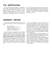
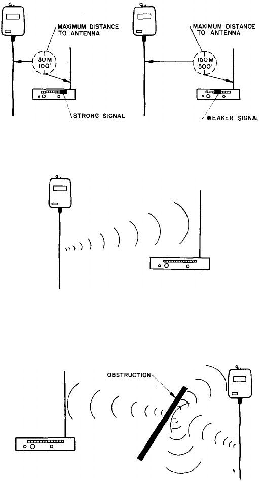
Try to avoid operating the system through or around
walls, ceilings, metal objects, etc. The usual result is
reduced range and performance, and the signal
reflections off metal obstructions will not only cause
reduced signal, but will introduce the problem of
multipath distortion (see Figure 8).
TRANSMITTER-RECEIVER DISTANCE
FIGURE 6
LINE-OF-SIGHT TRANSMISSION
FIGURE 7
OBSTRUCTION EFFECTS
FIGURE 8
13