


11
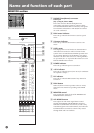
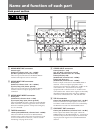
INSERT
MONO INPUT
5
LINE
MIC
INSERT
6
LINE
MIC
INSERT
3
LINE
MIC
INSERT
4
LINE
MIC
INSERT
1
LINE
MIC
INSERT
2
LINE
MIC
1
2
3
4
5
6
2
MONO INPUT
1
INSERT
9
LINE
MIC
INSERT
7
LINE
MIC
TAPE
IN
1 47
3
2
GRP/
DIRECT
OUT
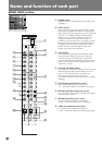
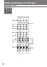
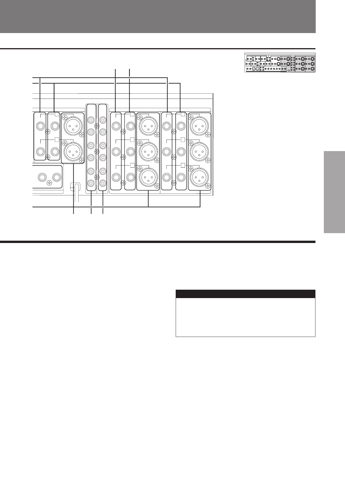
Name and function of
each part
!¡
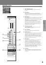
8 AUX OUTPUT connectors
Phone jacks (Unbalanced, reference level: +4 dBu)
9 2TR OUT connectors
Phono jacks (Unbalanced, reference level: –10 dBu)
These distribute and output the MASTER OUTPUT L/
R signals. They are connected to DAT or MD recorders,
or equivalent.
!º MONITOR OUT connectors
Phone jacks (Unbalanced, reference level: +4 dBu)
These output the same signals as the PHONES
connector, and signals from any channels whose PFL
or AFL buttons are turned on can be confirmed.
!¡ MASTER OUTPUT connectors
XLR-3-32 type
(Balanced, reference level: +4 dBu)
(Pin No. 1: ground, No. 2: hot, No. 3: cold)
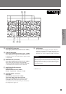
!™ MASTER INSERT connectors
Phone jacks
(Unbalanced, reference level: –6 dBu)
(Tip: output, Ring: input, Sleeve: ground)
These are the INSERT IN/OUT connectors of the
MASTER OUTPUT. External equipment can be
inserted before the L/R fader. They are connected to
the compressor or gate, etc.
!£ +48 V button
This is the button to supply power (DC +48 V) for
condenser microphones to the MIC connectors of the
MONO INPUT channels 1 - 8. When this button is
turned on, DC +48 V is output to all MIC connectors.
Caution
• Before turning on the +48 V button or after changing the cable
connection, turn down the output fader or the output volume.
• The line equipment must be connected to the LINE input side.
• When a dynamic microphone is used in conjunction with a
microphone that uses +48 V power, the dynamic microphone
may under-perform.
* 0 dBu=0.775 V