


7
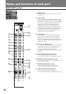
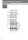
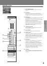
1 –10 dBs button
When this button is turned off, the reference input
level is +4 dBu; and when it is turned on, it is –10 dBu.
2 HIGH (High equalizer) level control
This varies the high equalizer level between
–15 - +15 dB. The equalizer is a 12 kHz shelving type.
3 MID (Mid equalizer) level control
This varies the mid equalizer level between
–15 - +15 dB. The equalizer is a 2.5 kHz peaking type.
4 LOW (Low equalizer) level control
This varies the low equalizer level between
–15 - +15 dB. The equalizer is a 40 Hz peaking type.
5 AUX 1-2 control
This controls the level to be sent to AUX 1/2 buses. The
signal that has been input to L is routed through the
AUX 1 bus, while the signal that has been input to R is
routed through the AUX 2 bus. This AUX is a pre-
fader (splitting the signal before the channel fader).
Thus, this is used to create a separate balance mix and
stereo monitor, as it does not depend on the position of
the channel fader.
6 AUX 3 and 4 controls
These control the levels to be sent to the AUX 3/4
buses. In this case, the L and R signals are mixed. This
AUX can switch between the pre-fader and post fader
(which splits the signal after the channel fader) using
the PRE button. (Refer to the MASTER section “2 PRE
button”)
7 AUX 5/7 and 6/8 controls
These control the levels that are sent to the
AUX 5/7 and 6/8 buses. In this case, the L and R
signals are mixed. These AUX’s are post faders. As a
result, the AUX level changes depending on the
position of the channel fader. This is used when
sending signals to the effector, etc. to be connected
externally.
8 AUX 7/8 button
These output the signals to the AUX 5/6 buses when
turned off, and to the AUX 7/8 buses when turned on.
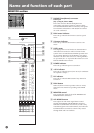
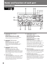
ST1 - ST4 channels
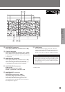
ST5 - ST8 channels
9 ON button
When turned on, the signals from the channels are
routed to each output. However, the PFL function is
available even if this switch is turned off.
!º Balance control
When turned in the “L ODD” direction, sound is
shifted to the MASTER L, GROUP 1, 3, 5, and 7 (odd
channel) buses, and when turned in the “R EVEN”
direction, sound is shifted to the MASTER R, GROUP
2, 4, 6, and 8 (even channel) buses. When turned to the
maximum in either direction, the output level is
increased by +3 dB.
!¡ PFL button
When turned on, the signals in stereo before they pass
through the channel fader are routed to the PHONES
connector and the MONITOR OUTPUT connectors,
while displaying the level on the meter. When PFL
buttons for a number of channels are pressed
simultaneously, the mixed signal is routed. In this case,
signals from channels whose AFL button is turned on
are not output.
!™ PEAK indicator
This is lit up whenever the signal level, after passing
through the equalizer, is within 3 dB of the maximum
level. When this LED is lit, the signal is excessive, and
must be controlled using the LEVEL control.
!£ Assign buttons
When the L-R button is pressed, the signal is routed to
the MASTER L/R buses, and when the 1/2, 3/4, 5/6,
or 7/8 buttons are pressed, the signal is routed to each
group bus.
!¢ Channel fader
This sets the signal level for the channels.
ST5 - ST8 channels are auxiliary stereo input channels.
Signals from these channels are only routed to the MASTER
L/R buses.
!∞ Channel volume control
This controls the level that is routed to the MASTER L/
R buses.
Name and function of
each part