8
Name and function of each part
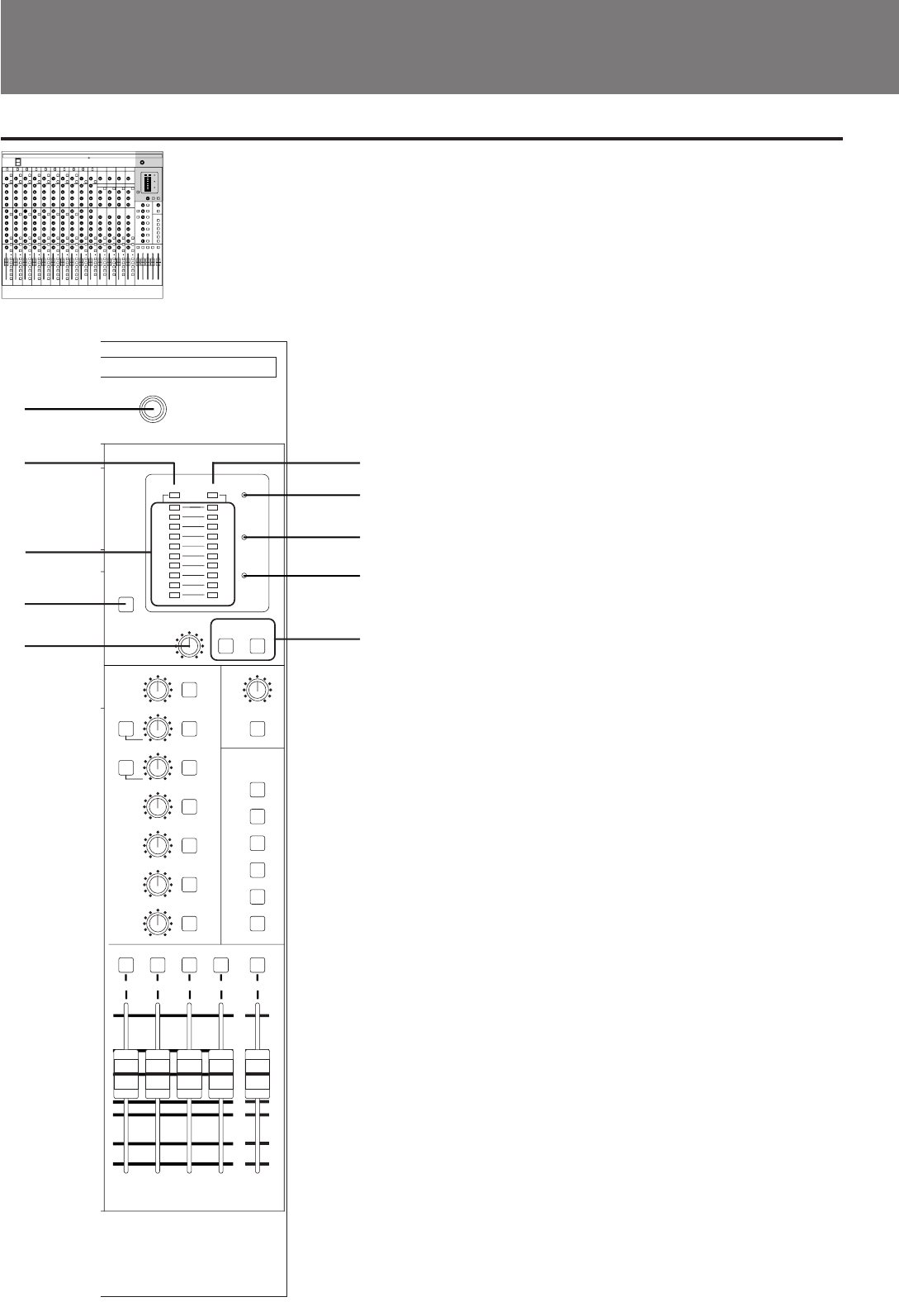
MONITOR section
1 PHONES (headphones) connector
Phone jack
(Tip: L, Ring: R, Sleeve: GND)
This is the connector that the headphones are
connected to. The same signals are output as those
from the MONITOR OUTPUT connectors, and signals
from channels whose PFL or AFL buttons are turned
on can be confirmed.
2 PEAK meter indicator
This is lit up when the level meter is used as a peak
meter.
3 VU meter indicator
This is lit up when the level meter is used as a VU
meter.
4 LEVEL meter
This displays the level of whichever channels PFL or
AFL buttons are turned on. The level meter in this
system can be switched between PEAK operation and
VU operation. Whichever of the PEAK or VU meters
indicator is lit shows the scale to use. During PEAK or
VU operation, the “0 ” represents the reference level in
both the PEAK and VU meters.
5 POWER indicator
This is lit up when the power is turned on.
6 +48 V indicator
This is lit up when the power (DC +48 V) for condenser
microphone is output.
7 PFL indicator
This is lit up when the PFL button of any channel is
turned on.
8 PEAK button
When off, the level meter operates as the VU meter,
and when on it switches to operating as the PEAK
meter.
9 MONITOR control
This controls the output levels of the PHONES and
MONITOR OUT connectors.
!º AFL MONO buttons
This outputs an AFL mono signal that is routed
through the PHONES and MONITOR connectors.
When the L/ODD button is turned on, sound is only
routed through the L and odd channels, and when the
R/EVEN button is turned on, sound is only routed
through the R and even channels.
1-2 3-4 5-6
7-8
2TR IN
L-R
8
1-2
3
4
5
6
7
AFL
PFL
+3
+1
0
-1
-3
-5
-7
-10
-20
PEAK VU
L
R
+5
+13
+11
+10
+9
+7
+5
+3
0
-10
+15
POWER
MONITOR
AUX MASTER
+48V
PHONES
AUDIO MIXER SRP-V110
-∞
+10
0
+5
+10
-5
-10
-20
- ∞
0
-∞
+10
0
-∞
+10
0
-∞
+10
0
-∞
+10
0
-∞
+10
0
-∞
+10
0
-∞
0
-∞
0
1
2
4
8
9
7
6
5
3
AFL MONO
L/ODD R/EVEN
PEAK
AFL AFL AFL AFL AFL
AFL
AFL
AFL
AFL
AFL
AFL
AFL
PRE
PRE
2TR IN
AUX 1-2
GRP1-2
GRP3-4
GRP5-6
GRP7-8
TO L-R
!º


