8
Fig. 1
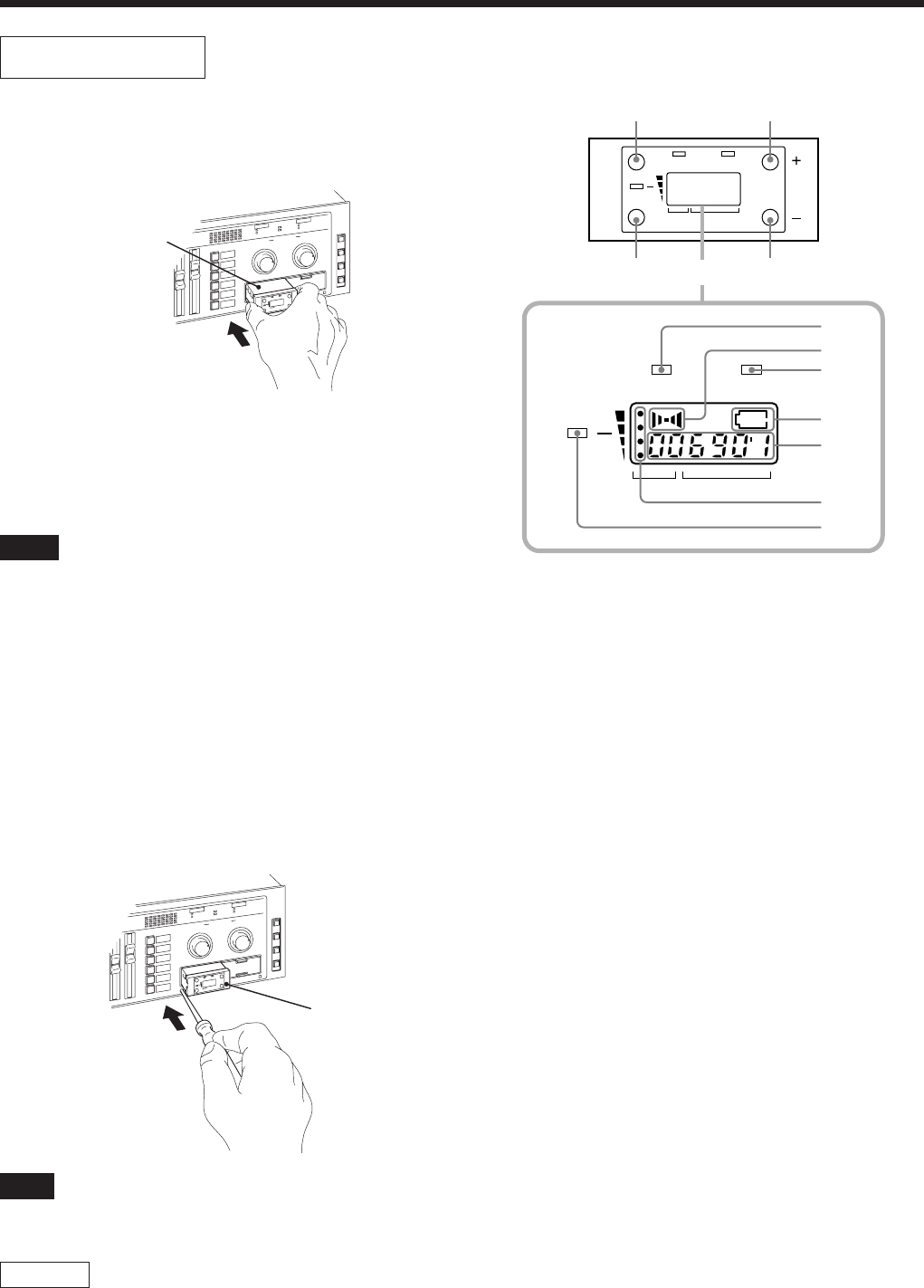
Fig. 2
Location and function of parts
Tuner Unit
How to install the tuner unit
1 Turn off the power of this unit.
2 Remove the tuner cover.
3 Check the up and down sides of the tuner unit, and insert it into
the slot. (Fig. 1)
4 After installation of the tuner unit, turn on the power of the unit
and turn on the power of the wireless microphone to check it is
receiving. While receiving, the RF/SIGNAL indicator lights
up. The RF/SIGNAL indicator will not light up when the
setting channel of the microphone is different from the setting
of the tuner unit, or when the microphone power is consumed.
Notes
Take the following precautions to prevent interference and noise.
• If there is a TV broadcasting station nearby, to avoid possible
interference from its broadcasting, do not use that station’s channel.
• When simultaneously using two tuners, always set the tuners to
different channels within the same group (other than group 00).
• Please make a choice of model in accordance with your area to
use picking up an unused TV channel.
• Make sure that the channel selected on the microphone is the
same as that selected on the tuner being used in the same system.
How to remove the tuner unit
1 Turn off the power of this unit.
2 Insert a screwdriver having the shaft diameter of 2 to 4 mm or
less with shaft length of 30 mm or longer, into the hole under
the lower part of the tuner slot as shown. Remove the tuner
unit. (Fig. 2)
Note
Insert it deeply into the slot.
Do not insert or remove the tuner unit while the power is on. This
may cause noise.
CAUTION
To prevent breakdown or injury, do not put your hand inside of the
slot.
Please refer to the table Sony 800 MHz-band system models
frequency range in the Operating Manual of Wireless Microphone
or Transmitter.
1 GP (group) button
To change the group, press the + or – button while holding this
button down.
2 CH (channel) button
To change the channel in a group, press the + or – button while
holding this button down.
3 + button
To go to a higher group or channel, press this button while
holding the GP or CH button.
Press this button changes the indication from GP/CH to
frequency.
4 – button
To go to a lower group or channel, press this button while
holding the GP or CH button.
5 AF (audio frequency) indicator
6 AF (audio frequency) level indications
The indicator lights and the indications appear when the audio
output level is higher than the reference level.
7 BATT (battery) indicator
8 BATT (battery) indication
Indicate the condition of the wireless microphone transmitter
batteries. The indicator and indication appear and start
flashing about one hour before the transmitter batteries go flat.
The time at which flashing begins will depend on the type of
battery used in the transmitter, and its condition.
9 GP/CH (group/channel) indication
Shows the reception channel group and respective channel
number.
Pressing the + button changes this indication to the frequency
indication.
0 RF (ratio frequency) level indications
qa RF (ratio frequency) indicator
The indicator lights and the indications (dots) appear when the
antenna reception is optimal. Depending on the RF input level,
the number of dots changes.
MASTER
SCE
NE
R
ECAL
L
GP
A
F
R
F
G
P
C
H
B
A
T
T
LINE 4 SELECT
A
A
B
C
D
E
F
B
Tuner unit
MASTER
SC
ENE
RE
CA
LL
GP
A
F
R
F
G
P
C
H
B
A
T
T
LINE 4 SELECT
A
A
B
C
D
E
F
B
Tuner unit
RF
AF
Display
GP CH
BATT
GP
AF
GP CH
BATT
CH
RF
24
13
5
6
7
8
9
0
qa


