Specifications are subject to change without notice
AtlasSound.com
1601 JACK MCKAY BOULEVARD ENNIS, TEXAS 75119 U.S.A. • TELEPHONE: (800) 876-3333 • FAX: (800) 765-3435
©2006 ATLAS SOUND LP Printed in U.S.A. 000106 ATS002171 RevA 01/06 PP
OWNER'S MANUAL
AA35 MIXER AMPLIFIER
6
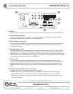
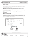
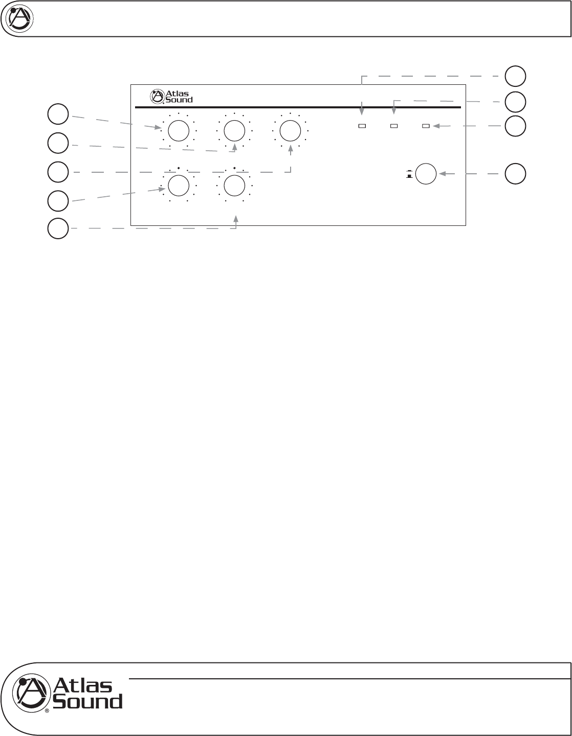
FRONT PANEL DESCRIPTION
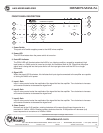
1. Power Switch
This push on/off switch supplies power to the AA35 mixer amplifi er.
2. Power LED
This LED illuminates when the power switch is turned on.
3. Peak LED Indicator
The PEAK LED will illuminate when the AA35 is in a clipping condition, caused by excessively high
input levels or a GAIN control is turned up too high. An occasional fl ash is OK. Check that the proper
signal level is being fed into the inputs and/or turn the input gain down until the LED is no longer
illuminated.
4. Signal LED
When the signal LED illuminates, this indicates that input signals connected to the amplifi er are capable
of driving the AA35 to full power.
5. Input 1 Gain
Input 1 rotary control varies the amplitude of the signal fed into the amplifi er. Turn clockwise to increase
and counter-clockwise to decrease the signal level.
6. Input 2 Gain
Input 2 rotary control varies the amplitude of the signal fed into the amplifi er. Turn clockwise to increase
and counter-clockwise to decrease the signal level.
7. Input 3 Gain
Input 3 rotary control varies the amplitude of the signal fed into the amplifi er. Turn clockwise to increase
and counter-clockwise to decrease the signal level.
8. Bass Control
Normally set at the 12:00 position, rotating clockwise will increase (boost) bass frequencies to a
maximum of 10dB at 100Hz. Rotating counter-clockwise from the 12:00 position will decrease (cut)
bass frequencies to a maximum of 10dB at 100Hz.
Power
On
Off
Signal PowerPeak
Treble
n
Bass
Input 3Input 2Input 1
n
77)+C_n[h7cfb_\_[h
5
8
9
1
2
3
4
6
7


