


Specifications are subject to change without notice
AtlasSound.com
1601 JACK MCKAY BOULEVARD ENNIS, TEXAS 75119 U.S.A. • TELEPHONE: (800) 876-3333 • FAX: (800) 765-3435
©2006 ATLAS SOUND LP Printed in U.S.A. 000106 ATS002171 RevA 01/06 PP
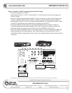
OWNER'S MANUAL
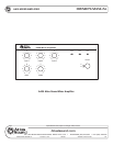
AA35 MIXER AMPLIFIER
9
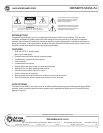
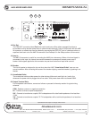
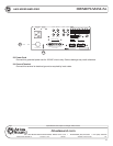
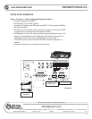
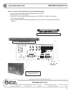
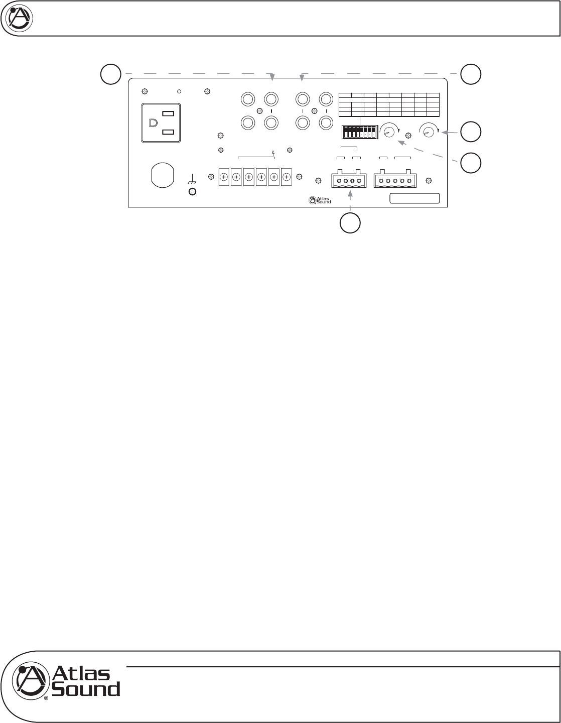
13. Input 3
Input 3 consists of stereo summing inputs, suitable for connection to the output of CD/DVD players, etc.
14. Zone 2 Output Connector
Use the 1W 8Ω terminals for connection to an external speaker. The 600Ω 1.5V output is typically
connected to a PBX music on hold port, also known as MOH.
15. Zone 2 Output Level Control
This rotary control will vary the signal level at the Zone 2 output terminals. Fully counter-clockwise (0)
is off, fully clockwise (10) is the maximum output level. The Zone 2 level control is PRE Inputs 1, 2,
and 3 volume controls.
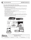
16. Mute Sensitivity Control
VOX Mute Sensitivity Control adjusts how sensitive the mute send circuitry on Input 1 reacts. Setting
the control fully counter-clockwise will lower the sensitivity, where a higher amplitude signal will be
required at Input 1 to trigger the mute send circuits. Fully clockwise will raise the sensitivity of the mute
circuits, where a lower amplitude signal will trigger a mute send. Careful calibration of this control may
be required to fully utilize the mute circuits capabilities.
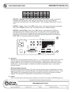
17. Line Out A/B
Line Out connectors A/B are paralleled jacks and are useful for providing unbalanced line level
signal to another amplifier or other external devices. Prior to using this feature one must understand
where the internal signal pick up point is so you can decide if it is correct for your application. We
suggest you refer to the block diagram of the AA35 to have a complete understanding of the signal
flow.
Note The Following Conditions For Line Out A/B
A. Post Low Cut Filter and is affected when filter is engaged.
B. Post Tone Controls (meaning the settings for the Bass and Treble controls affect this signal
output). Note: Refer to Low Cut Filter Switch for complete understanding of the LCF feature.
C. Post Amp In (meaning any signal that is inserted into the Pre AMP In jack will be present at the
Line Out A and B).
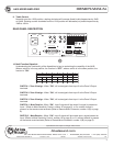
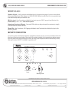
On
Off
Low cut
8
On
Off
43
21
Phantom
Mute Rcv
Off
On
Off
On
Off
On
Off
On
5
Zone 2 Assign
6
Input 3 Input 2 Input 1
Input1
7
Input 2
Input 3
Line/Tel
Mic
Off
On
Unswitched Outlet
120V AC 60Hz
Max 500W
Outlet Breaker
125V AC 4A
Push Reset
120V AC 60Hz 100W
Amp In
Line Out A
Line Out B
Pre Out
Input 3 Input 2
L
R
Zone2
100
Level
Mute
Sens
100
Remote
Mute
G-+
Input 1
¡
8
1W
¡
600
Zone 2 Out
-+-+
Speaker Output 35W
COM
25V
¡
8
70V
L
R
£Èä£Ê>VÊV>ÞÊÛ`°]ÊÃ]Ê/8ÊÇx££Ê
nää®ÊnÇÈÎÎÎÎÊÌ>Ã-Õ`°V
77)+
7jbWiIekdZ77I[h_[iC_n[h7cfb_\_[h
CLASS 2 WIRING
13
14
15
16
17