


Specifications are subject to change without notice
AtlasSound.com
1601 JACK MCKAY BOULEVARD ENNIS, TEXAS 75119 U.S.A. • TELEPHONE: (800) 876-3333 • FAX: (800) 765-3435
©2006 ATLAS SOUND LP Printed in U.S.A. 000106 ATS002171 RevA 01/06 PP
OWNER'S MANUAL
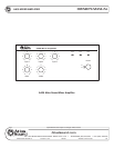
AA35 MIXER AMPLIFIER
8
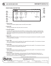
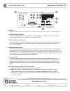
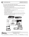
SWITCH 6 - Phantom - When "ON", applies Phantom Power 24VDC to Input 1 terminals for
condenser type microphones. Note: Only use this feature if you are using condenser
microphones, otherwise leave in the "OFF" position. This only applies when switch 7 is set to
"mic".
SWITCH 7 - Input 1 - When in the "MIC" position, Input 1 will accept microphone level signals;
when in the "Line/Tel" position, Input 1 will accept line level or telephone signals.
SWITCH 8 - Low Cut Filter - When in the "ON" position, frequencies below 400Hz are
attenuated at the rate of 6dB per octave. Note: The rotary bass control is bypassed when
the LOW CUT filter is on. We suggest that when paging horns are connected to the AA35,
engage the LOW CUT filter to prevent the horns from operating below their cutoff frequency.
When "OFF", the amplifier operates full bandwidth.
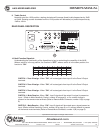
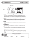
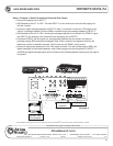
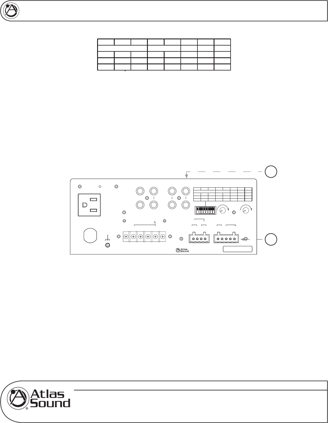
11. (A) Input 1
Balanced mic or line level signals connect to the (+), (—), and (G) terminals. Refer to the chart at the
top of the page for the following setting. Dipswitch number 7, labeled Input 1 must be set to the
proper position for mic or line level. If you are connecting an unbalanced line level input, tie (short)
the (G) and (—) terminals together. If transformer isolation is required for input 1, contact Atlas
Sound for details.
(B) Remote Mute Connector
Shorting the Remote Mute terminals, (G) to (M), will mute inputs 2 and/or 3, depending on how their
dipswitch settings are set for switch positions 4 and 5 labeled "Mute Rec"/"Input 2" & "Input 3". In the
"ON" position, the corresponding channel will be muted when terminals (G) and (M) are shorted
together. This connection is usually done via remote switch on a microphone.
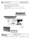
12. Input 2
Input 2 consists of stereo summing inputs, suitable for connection to the output of CD/DVD players, etc.
On
Off
Low cut
8
On
Off
43
21
Phantom
Mute Rcv
Off
On
Off
On
Off
On
Off
On
5
Zone 2 Assign
6
Input 3 Input 2 Input 1
Input1
7
Input 2
Input 3
Line/Tel
Mic
Off
On
On
Off
Low cut
8
On
Off
43
21
Phantom
Mute Rcv
Off
On
Off
On
Off
On
Off
On
5
Zone 2 Assign
6
Input 3 Input 2 Input 1
Input1
7
Input 2
Input 3
Line/Tel
Mic
Off
On
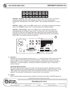
Unswitched Outlet
120V AC 60Hz
Max 500W
Outlet Breaker
125V AC 4A
Push Reset
120V AC 60Hz 100W
Amp In
Line Out A
Line Out B
Pre Out
Input 3 Input 2
L
R
Zone2
100
Level
Mute
Sens
100
Remote
Mute
G-+
Input 1
¡
8
1W
¡
600
Zone 2 Out
-+-+
Speaker Output 35W
COM
25V
¡
8
70V
L
R
£Èä£Ê>VÊV>ÞÊÛ`°]ÊÃ]Ê/8ÊÇx££Ê
nää®ÊnÇÈÎÎÎÎÊÌ>Ã-Õ`°V
77)+
7jbWiIekdZ77I[h_[iC_n[h7cfb_\_[h
CLASS 2 WIRING
11
12