


Transient Designer
11
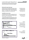
The ATTACK control circuitry incorporates two envelope genera-
tors.One follows the original curve while the second produces an
envelope with a slower attack period (Diagram 1,page 7).
The difference (Diagram 2, page 7) between these envelopes
results in a voltage that controls the VCA, boosting the transient
for a period equal to the duration of the original transient. The
amplitude of the attack is increased,if positive ATTACK values are
set, while negative ATTACK values reduce the level of the attack
transient. For detailed information about using the ATTACK
control please refer to pages 12ff.
The SUSTAIN control increases or reduces the level of the sustain
portion of a signal by up to 24dB.For detailed information about
the mode of operation of the sustain control please read the
'Tech Talk' section on pages 8 and 9.
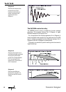
Two envelope generators work in the SUSTAIN control circuitry,
too. Again an envelope follower pursues the original envelope
and adapts optimally to the curve of sustain. This second gene-
rator produces an envelope with extended sustain (Diagram 4,
page 8). The difference between both envelopes is then used to
calculate the voltage controlling the VCA, though as with the
ATTACK circuitry,the enhancement ceases at the end of the signal
being processed.
Sustain amplitude is increased for positive SUSTAIN settings
and reduced for negative settings.For detailed information about
using the SUSTAIN control please refer to pages 12ff.
When processing stereo material, the LINK function should be
switched on so that the linked channels produce the same
degree of gain change, regardless of any difference in levels of
the two channels. This is necessary to maintain a coherent and
stable stereo image.
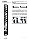
The front panel controls,including the A
CTIVE switch of channel
1 or 3,function as the master controls in LINK mode.
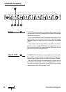
Control elements
Sustain
4
Attack
3
Link
5