


Transient Designer
6
Before connecting the TRANSIENT DESIGNER switch power off at all
connected units.
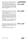
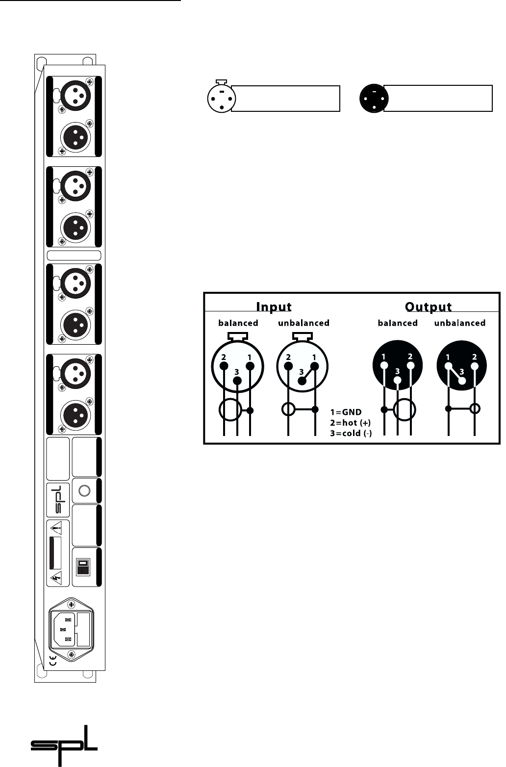
The T
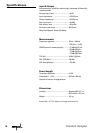
RANSIENT DESIGNER is fitted with XLR-connectors for balanced
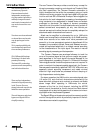
operation.The following illustration shows the pin-wiring:
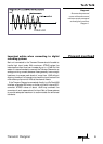
To ensure optimal signal quality,SPL has developed a new hybrid-
component balanced input/output stage using all laser-trimmed
resistors with a tolerance of 0.01%.This approach has resulted in
an exceptionally high CCMR (common mode rejection); -80dB at
1kHz and -75dB at 10 kHz.
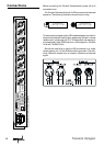
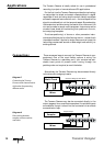
Should the need arise to use the XLR connectors in an unba-
lanced system, pin 3 of the XLRs should be grounded. The follo-
wing illustration shows how to properly unbalance a balanced
signal:
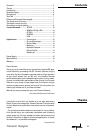
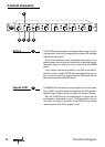
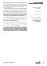
Rear panel TRANSIENT DESIGNER,model 9842
Connections
2
1
3
1
2
3
Pin wiring: XLR output
1 = GND, 2 = hot (+), 3 = cold (-)
Pin wiring: XLR input
1 = GND, 2 = hot (+), 3 = cold (-)
soundperformancelab.com
TO REDUCE RISK OF FIRE
OR ELECTRIC SHOCK DO
NOT EXPOSE THIS UNIT
TO RAIN OR MOISTURE.
DISCONNECT MAINS
BEFORE REMOVING COVER.
VOLTAGE/FUSE
XLR Wiring: 1 = GND/ 2 = (+)/ 3 = (–)
Output 4 Input 4 Output 3 Input 3 Output 2 Input 2 Output 1 Input 1
GND LIFT
AVIS: RISQUE DE CHOC ÉLECTRIQUE - NE PAS OUVRIR
RISK OF ELECTRIC SHOCK
DO NOT OPEN
CAUTION
Serial #
WARNING
Sound Performance Lab
SPL electronics GmbH
41372 Niederkrüchten
Germany
Made in Germany
230 V
50 Hz
Fuse:
200mA
115 V
60 Hz
Fuse:
400mA
230 V
Input 4 Output 4Input 3 Output 3Input 2 Output 2Input 1 Output 1