


18-CD22D1-8 27
Installer’s Guide
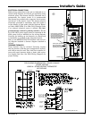
ELECTRICAL CONNECTIONS
Make wiring connections to the unit as indicated on en-
closed wiring diagram. As with all gas appliances using
electrical power, this furnace shall be connected into a
permanently live electric circuit. It is recommended
that furnace be provided with a separate “circuit protec-
tion device” in the electric circuit. The furnace must be
electrically grounded in accordance with local codes or
in the absence of local codes with the National Electri-
cal Code, ANSI/ NFPA 70 or CSA C22.1 Electrical Code,
if an external electrical source is utilized. The inte-
grated furnace control is polarity sensitive. The hot
leg of the 120V power supply must be connected to the
black power lead as indicated on the wiring diagram.
Provision for hooking up an electronic air cleaner and
or humidifier is provided on the integrated control.
Refer to the SERVICE FACTS literature and unit wir-
ing diagram attached to furnace diagram attached to
furnace.
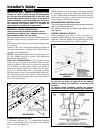
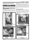
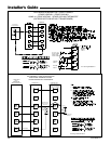
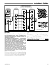
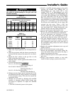
TWINNING FURNACES
These furnaces may be twinned. Twinning requires
that two furnaces with the same configuration, capacity,
and airflow must be used. They shall have common re-
turns with equal pressure drops or ducts with equiva-
lent lengths and sizes. See Field Wiring Diagrams for
proper hookup.
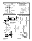
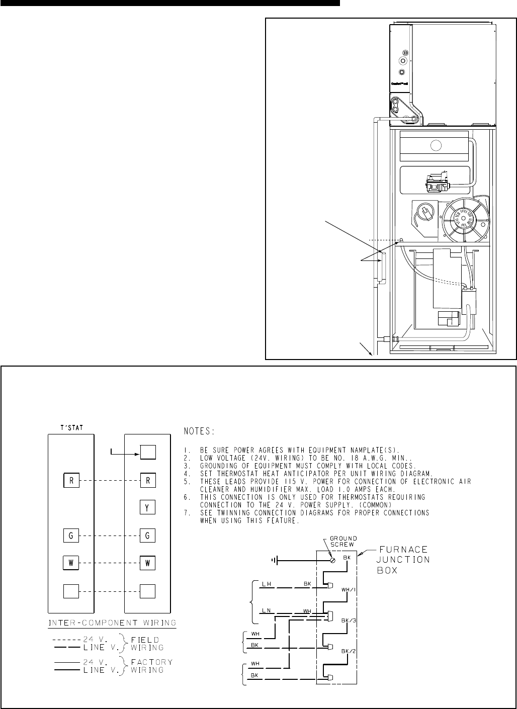
SEE
NOTE 6
From drawing B341437 Rv 1
FURNACE
TWIN
SEE
NOTE 7
B/C
B/C
TO 115 V 1 PH.,
60 HZ., POWER
SUPPLY PER
LOCAL CODES
HUM SEE
NOTE 5
EAC SEE
NOTE 5
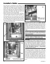
FIELD WIRING DIAGRAM FOR 1 STAGE FURNACE
1 STAGE HEATING
USING A 1 STAGE HEATING THERMOSTAT
NO COOLING
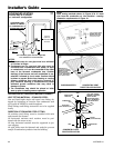
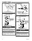
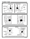
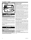
Primary drain vent stack
must terminate below
secondary heat exchanger
condensate drain outlet.
To drain opening
If upflow furnace is installed
over a finished ceiling, overflow
from the primary drain vent
stack must flow into an auxillary
drain pan to prevent damage to
the finished ceiling below.
&