


18-CD22D1-8 33
Installer’s Guide
ANSI Z223.1/ NFPA 54 or National Standard of
Canada, Natural Gas and Propane Installation Code,
CSA B149.1. Installation of this furnace at altitudes
above 2,000 ft. (610m) shall be made in accordance with
the listed high Altitude Conversion Kit available with
this furnace.
IMPORTANT:
Re-install the propane orifices to the same depth as the
orifices supplied with the equipment.
See Table 15 for help in selecting orifices if orifice
change is required. Furnace input rate and tempera-
ture rise should be checked again after changing ori-
fices to confirm the proper rate for the altitude.
Installations above 4,000 feet may require a pressure
switch change. If required, use the BAYHALT*** Kit
(High Altitude Accessory Kit) listed in PRODUCT DATA.
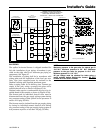
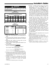
TABLE 14
PART NUMBERS FOR REPLACEMENT ORIFICES
DRILL
SIZE
PART
NUMBER
DRILL
SIZE
PART
NUMBER
44
45
46
47
48
49
50
ORF00501
ORF00644
ORF00909
ORF00910
ORF01099
ORF00503
ORF00493
54
55
56
57
58
59
ORF00555
ORF00693
ORF00907
ORF00908
ORF01338
ORF01339
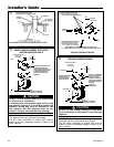
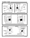
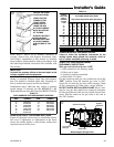
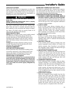
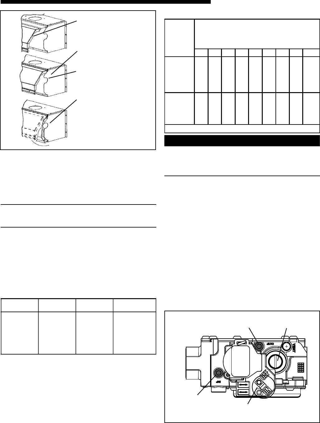
REINSTALLATION OF THE BURNER BOX COVER
Figure 52 shows the correct way to reinstall the burner
box cover if adjustment or replacement of the flame
sensor, hot surface igniter, or main burner orifices have
required removal of the cover.
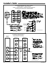
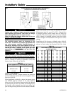
TABLE 15
Orifice
Twist Drill
Size If
Installed
At Sea
Level
ALTITUDE ABOVE SEA LEVEL
and Orifice Required At Other Elevations
2000 3000 4000 5000 6000 7000 8000 9000 10000
42
43
44
45
46
47
42
44
45
46
47
48
43
44
45
47
47
48
43
44
45
47
47
49
43
45
46
47
48
49
44
45
47
48
48
49
44
46
47
48
49
50
45
47
48
49
49
50
46
47
48
49
50
51
47
48
50
50
51
52
54
55
56
57
58
54
55
56
58
59
55
55
56
59
60
55
55
57
59
60
55
56
57
60
61
55
56
57
60
62
55
56
58
61
62
56
56
59
62
63
56
56
59
63
63
56
57
60
63
64
From National Fuel Gas Code - Table F-4
▲
WARNING
!
CARBON MONOXIDE POISONING HAZARD
Failure to follow the installation instructions for the
venting system being placed into operation could re-
sult in carbon monoxide poisoning or death.
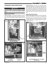
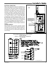
START UP AND ADJUSTMENT
PRELIMINARY INSPECTIONS
With gas and electrical power “OFF”
1. Duct connections are properly sealed
2. Filters are in place
3. Venting is properly assembled
4. Blower door is in place
Flip the switch on main gas valve within the unit to the
“OFF” position. Turn the external gas valve to “ON”.
Purge the air from the gas lines. After purging, Check
all gas connections for leaks with a soapy solution —
DO NOT CHECK WITH AN OPEN FLAME. Allow 5 min-
utes for any gas that might have escaped to dissipate.
LP Gas being heavier than air may require forced venti-
lation. Flip the switch on the gas valve in the unit to
the “ON” position.
W
ROTATE THE FRONT
COVER INWARD
MAKING SURE THAT
ALL SIDE FLANGES
ARE OUTSIDE OF THE
BOX.
INSERT THE TOP
FLANGE OF THE
FRONT COVER
UNDER THE LIP
INSIDE THE BOX
ALL SIDE FLANGES
MUST BE OUTSIDE
OF THE BOX
ROTATE THE FRONT
COVER AS SHOWN
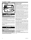
E
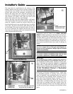
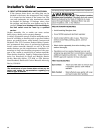
Outlet Pressure Boss
Regulator
Adjustment
White-Rodgers 36G gas valve
Inlet Pressure
Boss (opt.)
On/Off Switch