


18-CD22D1-8 35
Installer’s Guide
AIRFLOW ADJUSTMENT
Check inlet and outlet air temperatures to make sure
they are within the ranges specified on the furnace rat-
ing nameplate. If the airflow needs to be increased or
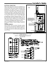
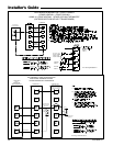
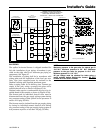
decreased, see the wiring diagram for information on
changing the speed of the blower motor.
▲
WARNING
!
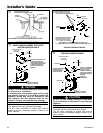
Disconnect power to the unit before removing the
blower door.
Failure to follow this warning could result in property
damage, personal injury or death.
This unit is equipped with a blower door switch which
cuts power to the blower and gas valve causing shut-
down when the door is removed. Operation with the
door removed or ajar can permit the escape of danger-
ous fumes. All panels must be securely closed at all
times for safe operation of the furnace.
INDOOR BLOWER TIMING
Heating: The integrated furnace control module controls
the indoor blower. The blower start is fixed at 45
seconds after ignition. The FAN-OFF period is field
selectable by dip switches at 60, 100, 140, or 180 sec-
onds. The factory setting is 100 seconds (See wiring
diagram).
Cooling: The fan delay off period is factory set at 0
seconds. The option for 80 second delay off is field
selectable (See wiring diagram).
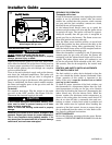
ROOM AIR THERMOSTAT
HEAT ANTICIPATOR ADJUSTMENT
Set the thermostat heat anticipator according to the
current flow measured, or the settings found in the
notes on the furnace wiring diagram (found in the
SERVICE FACTS or inside the furnace casing).
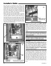
INSTRUCTIONS TO THE OWNERS
In the event that electrical, fuel, or mechanical failures
occur, the owner should immediately turn the gas sup-
ply off at the manual gas valve, located in the burner
compartment. Also turn off electrical power to the fur-
nace and contact the service agency designated by
your dealer.
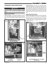
BURNER BOX TEMPERATURE LIMIT DEVICE
All models are equipped with a manual reset tempera-
ture limit located on the burner box. In case of exces-
sive temperature, the limit will open and cause the cir-
cuit to open which shuts off all flow of gas.
CONDITIONS AFFECTING FURNACE OPERATION
1. EXCESSIVE COMBUSTION PRESSURE (WIND IN
EXCESS OF 40 M.P.H.) VENT OR FLUE BLOCKAGE
If pressure against induced draft blower outlet be-
comes excessive, the pressure switch will open and
shut off the gas valve until acceptable combustion
pressure is again available.
2. LOSS OF FLAME
If loss of flame occurs during a heating cycle, or
flame is not present at the sensor, the flame control
module will close the gas valve. The flame control
module will then recycle the ignition sequence,
then if ignition is not achieved, it will shut off the
gas valve and lock out the system.
3. POWER FAILURE
If there is a power failure during a heating cycle,
the system will restart the ignition sequence auto-
matically when power is restored if the thermostat
still calls for heat.
4. GAS SUPPLY FAILURE
If loss of flame occurs during a heating cycle, the
system integrated control module will recycle the
ignition sequence, then if ignition is not achieved,
the integrated control module will shut off the gas
valve and lock out the system.
5. INDUCED DRAFT BLOWER FAILURE
If pressure is not sensed by the pressure switch, the
contacts will remain open and not allow the gas
valve to open, therefore the unit will not start. If
failure occurs during a running cycle, the pressure
switch contacts will open and the gas valve will
close to shut the unit down.
6. CONDENSATE DRAIN BLOCKAGE
If the condensate drain is blocked, either by debris,
improper draining, or by freezing condensate, the
pressure switch will sense the accumulation of con-
densate in the furnace drain pan. The pressure
switch contacts will open and remain open, not al-
lowing unit operation. The unit will not operate un-
til the condensate drain has been cleared, and the
condensate flows freely.
7. RESET AFTER LOCKOUT
When the integrated control module has shut the
system down and gone into lockout, the system
must be manually reset before the unit will restart.
To reset, turn the system power off, then on, then
off and then on again within 30 seconds. This may
be done at the unit’s power source or at the ther-
mostat. The system will not reset unless the proce-
dure off-on-off-on is completed within 30 seconds.