


12
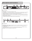
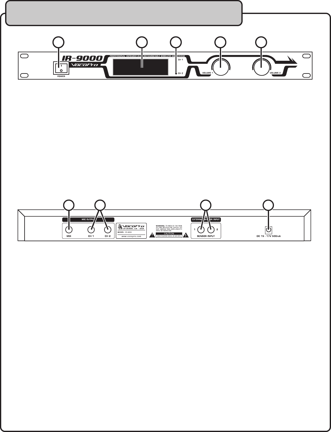
Receiver Front Panel
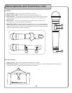
1. Power switch - Turns the receiver unit’s power on and off
2. Infrared Sensor - This is the built-in infrared sensor. Make sure there is a clear path between the microphones
and this sensor. For increased signal strength you can add up to two external infrared sensors. See the
getting connected section for instructions on connecting external infrared sensors.
3. LED Channel Indicators - Each of these two LED indicators will light up when the corresponding microphone is
switched on and an infrared connection is made to the IR-9000. The indicator(s) will remain lit as long as the
infrared connection is maintained.
4. Microphone Volume controls - Controls the volume for each microphone channel. Turn clockwise to raise the
microphone volume and counter-clockwise to lower the microphone volume.
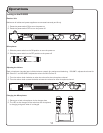
Receiver Rear Panel
1. Mixed Output ¼” jack - Outputs both microphone channels on a single channel using a ¼” microphone cable.
2. Independent Microphone Output
¼” jacks - Connect each microphone channel independently using a ¼”
microphone cable.
3. Infrared Sensor input jacks
- Connect up to two external infrared sensors here. The IR-9000 includes one
external infrared sensor. A second one can be purchased from your VocoPro dealer.
4. DC Input - Connect the DC adaptor here to power the unit.
Descriptions and Functions