


10 Front and rear panel
EMX860ST—Owner’s Manual
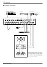
Input/output panel
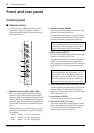
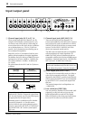
1 Channel input jacks (Hi-Z, Lo-Z) 1–6
These are the input jacks for channels 1–6. By
using the PAD switches (control panel 6) you
can connect any of the jacks to a wide range of
sources from mics to line level devices (synthesiz-
ers or rhythm boxes etc.). The Lo-Z jacks can
provide +48 V phantom power, allowing you to
use condenser microphones.
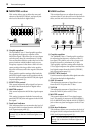
Both Hi-Z and Lo-Z are balanced, and are com-
patible with microphones of output impedance
50–600Ω or line level devices of 600Ω. The nom-
inal input level is from –40 dB to –10 dB for the
Hi-Z jacks, and from –50 dB to –20 dB for the
Lo-Z jacks.
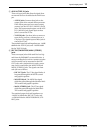
Pin connections for the Hi-Z and Lo-Z jacks are
as follows.
2 Channel input jacks (MIC/LINE) 7–8
These are the input jacks for channels 7–8.
Connect microphones to the MIC jacks. Connect
line-level devices, such as synthesizers to LINE L
(MONO)/R jacks if the devices are stereo sound
sources. Use the LINE L (MONO) jack if the
devices are monaural sound sources.
The MIC jacks are balanced, and are compatible
with microphones of output impedance 50–
600Ω. The LINE jacks are unbalanced, and are
compatible with line level devices of 600Ω output
impedance. Nominal input level is –50 dB for the
MIC jacks and –20 dB for the LINE jacks.
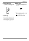
3 Effect output jack (EFFECT OUT)
The input of an external effect such as a delay or
echo can be connected to this jack. The signal
adjusted by the EFFECT control of each channel
will be sent to the EFFECT bus, its level adjusted
by the EFFECT OUT control, and output from
this jack.
The nominal output level and impedance are
+4 dB/10 kΩ.
4 Foot switch jack (FOOT SW)
You can connect a Yamaha FC5 foot switch (sold
separately) to this jack and use it to turn the
built-in digital effect on and off. The Digital
Effect ON switch on the front panel must always
be set to ON in order to use the foot switch.
REC
OUT
TAPE
IN
OUTPUT
L
LL
RR
RL
(MONO) R
MAIN(STEREO) MONITORAUX IN
POWERED MIXER
FOOT SW
MICLo-Z
Hi-Z
LINE
EFFECT
OUT
INPUT TO MAIN
LR
(MONO)
MIC
LINELR
(MONO)
Lo-Z
Hi-Z
Lo-Z
Hi-Z
Lo-Z
Hi-Z
Lo-Z
Hi-Z
Lo-Z
Hi-Z
21 43
56
Lo-Z jacks
(XLR type)
Hi-Z jacks
(TRS phone jacks)
Pin 1: ground Sleeve: ground
Pin 2: hot (+) Tip: hot (+)
Pin 3: cold (–) Ring: cold (–)
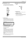
Note: It is not possible to simultaneously use
both the Hi-Z and Lo-Z inputs of a given chan-
nel. For each channel, use only one of the inputs
as appropriate for the input source.
Phantom power is switched on/off in simulta-
neously for channels 1–8. For this reason,
devices which do not require phantom power
must be connected to the Hi-Z or LINE jacks if
the PHANTOM +48 V switch (control panel
M) is on.
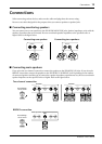
GND
RST
+-
GND
+-
Note: The MIC and LINE inputs for channel 7
can be used simultaneously but their levels can-
not be adjusted separately (Same for channel 8.)