


8
Front and rear panel
EMX860ST—Owner’s Manual
■
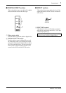
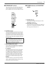
MONITOR section
This section allows you to adjust the tone and
volume of the MONITOR bus, and specify the
mix level of the built-in digital effect.
0
Graphic equalizer
The EMX860ST has a 7-band graphic equalizer
for adjusting the frequency response of the
MONI bus signal. This allows you to cut or boost
each frequency band by a maximum of
±
12dB.
You can use these sliders to reduce the level of fre-
quency bands at which feedback easily occurs.
Frequency response is flat when a slider is in the
center position. Moving a slider in the positive
direction will boost, and in the negative direction
will cut.
These graphic equalizer settings affect both the
MONI bus signal output to the speakers and the
line level signal sent from MONITOR jack signal
(input/output panel
6
).
A
EFFECT RTN control
This control adjusts the effect signal level sent to
the MONI bus from the built-in digital effect.
B
MASTER control
This control adjusts the MONI bus signal output
level.
This setting is output to both the front and rear
panel MONITOR jacks and appears in the MONI
bus signal.
C
Peak level indicator
This indicator allows you to monitor the level of
the signal which is output from the MONITOR
jack (input/output panel
6
).
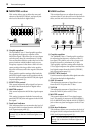
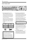
■
MAIN section
This section allows you to adjust the tone and
volume of the ST bus, the mix level of the built-in
effect, and the mix level of the external input.
D
Graphic equalizer
The EMX860ST has a 7-band graphic equalizer
for adjusting the frequency response of the ST
bus signal. This allows you to cut or boost each
frequency band by a maximum of
±
12dB.
These graphic equalizer settings affect both the
ST bus signal output to the speakers and the line
level signal output from the MAIN (STEREO)
jack (input/output panel
6
).
E
EFFECT RTN control
Use this control to adjust the effect signal sent to the
ST bus from the built-in digital effect.
F
AUX IN control
This adjusts the amount of signal that is sent
from the AUX IN jack to the ST bus.
G
TAPE IN
This adjusts the amount of signal that is sent
from the TAPE IN jacks to the ST bus.
H
MASTER control
This control adjusts the ST bus signal output
level. This setting is output to the SPEAKERS L/
R/L+R, BRIDGE jacks and the MAIN (STEREO)
jack on the rear panel and appears in the ST bus
signal.
I
Peak level indicator
This indicator allows you to monitor the level of
the signal which is output from the MAIN (STE-
REO) jack (input/output panel
6
).
Note:
To avoid distortion, adjust the MASTER
control (
B
) so that the 0 indicator lights occa-
sionally.
010
+6
+3
0
–5
–10
•
6
•
0
•
6
•
MASTER
EFFECT RTN
MONITOR
125 250 500 1k 2k 4k 8k
–12
+12
•
6
•
0
•
6
•
–12
+12
010
C
A
B
0
Note:
To avoid distortion, adjust the MASTER
control (
H
) so that the 0 indicator lights occa-
sionally.
+6
+3
0
–5
–10
LR
MAIN STEREO
MASTER
EFFECT RTN AUX IN TAPE IN
125 250 500 1k 2k 4k 8k
•
6
•
0
•
6
•
–12
+12
•
6
•
0
•
6
•
–12
+12
010
D
I
H
E
F
G
010010
010