


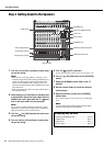
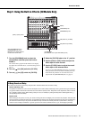
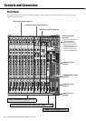


Controls and Connectors
MG20XU/MG20/MG16XU/MG16/MG12XU/MG12 Owner’s Manual
18
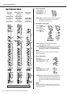
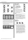
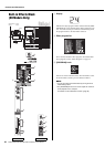
!0 Equalizer ([HIGH]/[MID]/[LOW])
Equalization Types and Characteristics
The equalizer shapes the high, mid, and low audio frequen-
cies. Turning the knob to the right amplifies (boosts) the cor-
responding frequency band, while turning it to the left
attenuates (cuts) the band. Setting the knob to the middle “t”
position produces a flat response in the corresponding band.
The upper knob sets the variable mid frequency, while the
lower knob sets the amount of attenuation or boost (counter-
clockwise/clockwise) for the range.
The following table shows the EQ type, frequency, and cut/
boost range for each of the three bands.
* The signals from mono input jacks of the MG20XU/MG20
and MG16XU/MG16 can be adjusted from 250 Hz to 5 kHz.
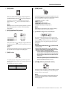
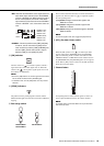
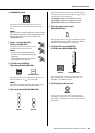
!1 [AUX 1 – 4] knobs
[PRE] switches
[AUX (2, 4)/FX] knobs
The levels of each signal sent to the AUX 1 –
4 buses from each channel can be adjusted
independently. On stereo input channels, the
Line L (odd) and Line R (even) input signals
are mixed before being sent to each AUX
bus. Adjust the knobs so that they are near or
at the “t” (nominal) position.
NOTE
• The [AUX1] knob indicated “PRE” adjusts the level of the pre-
fader signal (before fader adjustment).
• The [PRE] switch on [AUX1] and [AUX2] can be used to
select whether the pre-fader ( ) (the signal before fader
adjustment) or post fader ( ) (the signal after fader adjust-
ment) signal is sent to the AUX bus by the [PRE] switch.
• The [AUX4/FX] and [AUX2/FX] knobs are used to adjust the
level of the signal sent to the FX bus (built-in effects) in addi-
tion to the AUX bus. The same signal level is sent to the AUX
buses and FX buses connected to these knobs.
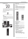
!2 [PAN] knobs
[PAN/BAL] knobs
[BAL] knobs
• PAN: Sets the position of the sound image within the
stereo field. This knob adjusts the volume bal-
ance of each channel sent to the STEREO L/R
bus. When the knob is set to the 12 o’clock posi-
tion, the channel’s sound will be sent to the L and
R of the STEREO L/R bus at the same volume. In
this case, the sound image is positioned at the
center. If the bus assign switch [1-2] or [3-4] is
pressed, this knob adjusts the volume balance
sent to the GROUP bus. When the knob is set to
the 12 o’clock position, the same volume is sent
to each GROUP bus. If the knob is turned com-
pletely to the left, the signal is sent to the GROUP
1 or GROUP 3 bus only; if the knob is turned
completely to the right, the signal is sent to the
GROUP 2 or GROUP 4 bus only.
3 Band
[MID] Sweep
3 Band 2 Band
MG20XU/
MG20
CH 1 – 12
CH 13/14 –
19/20
—
MG16XU/
MG16
CH 1 – 8
CH 9/10 –
15/16
—
MG12XU/
MG12
— CH 1 – 7/8
CH 9/10 –
11/12
Band Type Frequency
Cut/Boost
range
HIGH Shelving 10 kHz
±15 dBMID Peaking 2.5 kHz*
LOW Shelving 100 Hz
3 Band
[MID] Sweep
3 Band 2 Band
MG20XU/MG16XU: [AUX1],
[AUX2 – 3], [AUX4/FX]
MG20/MG16: [AUX1], [AUX2 – 4]
MG12XU: [AUX1], [AUX2/FX]
MG12: [AUX1 – 2]