


Editing a Performance
MOTIF XS Owner’s Manual
148
Voice mode Song mode Pattern mode Mixing mode Master mode Utility mode File mode
Performance
mode
Sampling
mode 1
Sampling
mode 2
Reference
R mono
Only the R channel of the audio input is used.
L+R mono
The L and R channels of the audio input are mixed and processed in
mono.
stereo
Both the L and R channels of the audio input are used.
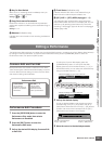
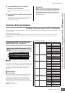
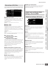
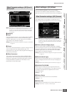
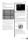
4 Output Select
Determines the output jack assignment for the Audio Input
Part.
Settings: See the table below.
n You can call up the list and select the desired item by pressing
the [SF6] LIST button. For details, see page 82.
5 Reverb Send
Determines the Send level of the Audio Input Part signal
sent to the Reverb effect. The higher the value, the deeper
the reverb.
Settings: 0 – 127
6 Chorus Send
Determines the Send level of the Audio Input Part signal
sent to the Chorus effect. The higher the value, the deeper
the Chorus.
Settings: 0 – 127
7 Dry Level
Determines the level of the Audio Input Part which has not
been processed with the System Effects (Reverb, Chorus).
The higher the value, the shallower the Reverb and Chorus.
Settings: 0 – 127
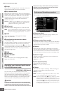
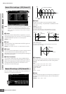
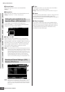
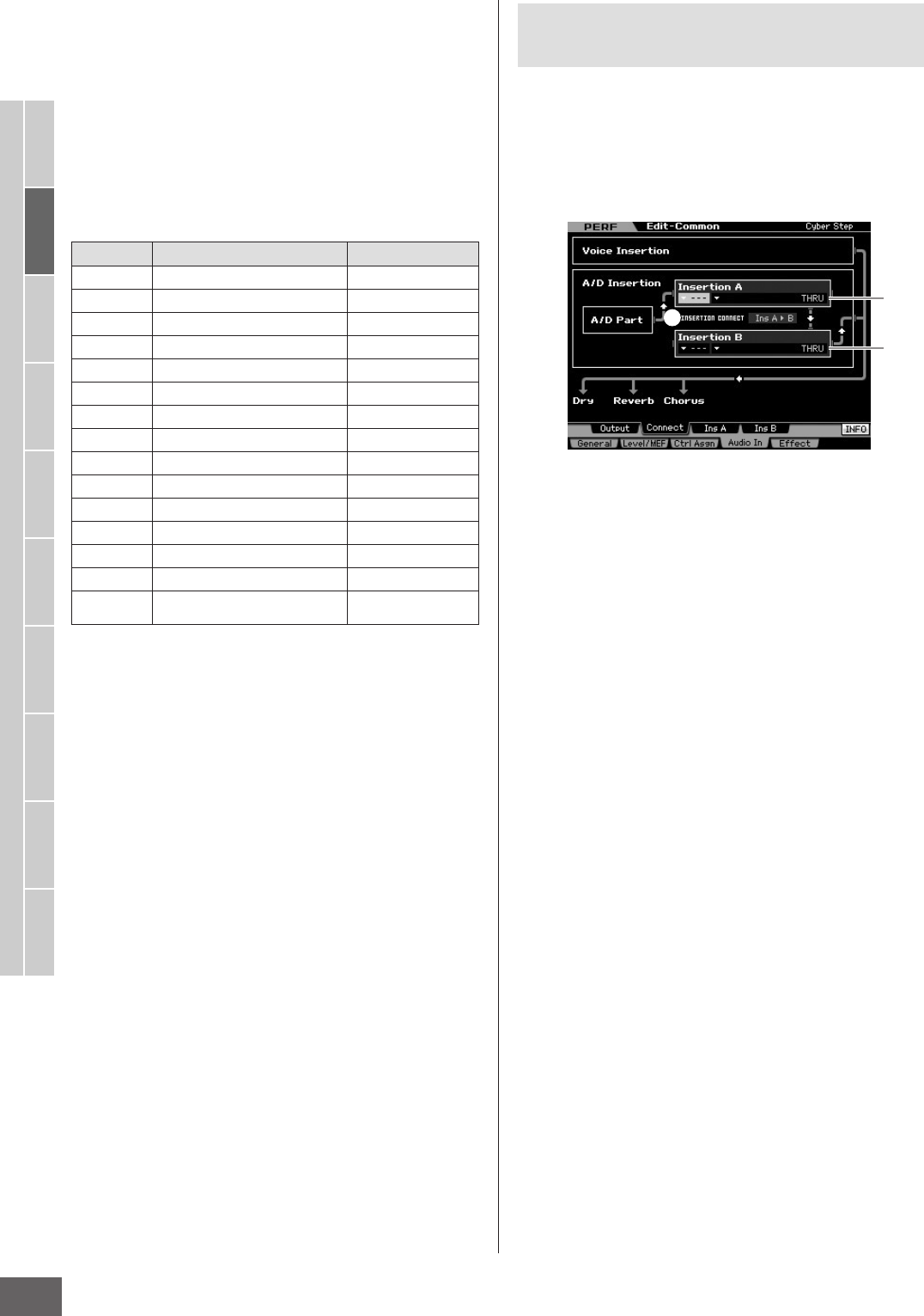
From this display, you can set the Insertion Effect Types
applied to the Audio Input signal in the Performance mode.
The System Effect can be set in the Effect display
(page 149). Keep in mind that the Insertion Effect cannot
be applied to the audio input signal via the mLAN
connector.
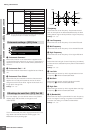
1 INSERTION CONNECT (Insertion Connection)
From this display you can set the effect routing for Insertion
effects A and B. The setting changes are shown on the
diagram in the display, giving you a clear picture of how
the signal is routed.
Settings: Ins A F B, Ins B F A
Ins A F B (A to B)
Signals processed with the Insertion Effect A will be sent to the
Insertion Effect B and signals processed with the Insertion Effect B is
sent to Reverb and Chorus.
Ins B F A (B to A)
Signals processed with the Insertion Effect B will be sent to the
Insertion Effect A and signals processed with the Insertion Effect B is
sent to Reverb and Chorus.
2 Insertion A (Insertion A Category/Type)*
3 Insertion B (Insertion B Category/Type)*
Determines the Effect type for Insertion A and B. From the
Category column, you can select one of the Effect
Categories, each of which contains similar Effect types.
From the Type column, you can select one of the Effect
Types listed in the selected Category.
Settings: Details about the Effect categories and types are described
on page 70.
n You can call up the list by pressing the [SF6] LIST button then
select the desired one from the list. For details, see page 82.
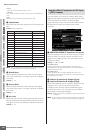
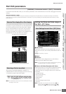
LCD Output jacks Stereo/Mono
L&R OUTPUT L and R Stereo
asL&R ASSIGNABLE OUTPUT L and R Stereo
m1&2 mLAN OUTPUT 1 and 2 Stereo (1: L, 2: R)
m3&4 mLAN OUTPUT 3 and 4 Stereo (3: L, 4: R)
m5&6 mLAN OUTPUT 5 and 6 Stereo (5: L, 6: R)
m7&8 mLAN OUTPUT 7 and 8 Stereo (7: L, 8: R)
m9&10 mLAN OUTPUT 9 and 10 Stereo (9: L, 10: R)
m11&12 mLAN OUTPUT 11 and 12 Stereo (11: L, 12: R)
m13&14 mLAN OUTPUT 13 and 14 Stereo (13: L, 14: R)
asL ASSIGNABLE OUTPUT L Mono
asR ASSIGNABLE OUTPUT R Mono
m1 mLAN OUTPUT 1 Mono
:: :
m14 mLAN OUTPUT 14 Mono
ins L
(A/D input only)
Internal Vocoder Module Mono
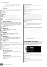
Insertion Effect Connection of A/D Input
—[SF2] Connect
2
3
1