


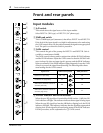
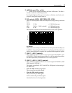
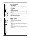
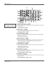

AUX SEND module
7
MX400 User’s Guide
AUX SEND module
1
AUX SEND fader
This adjusts the signal level of the AUX SEND output. A position at the zero
(0) marking is the nominal level. Raising the fader above 0 provides up to
10dB of gain.
2
PEAK indicator
This indicator lights when the level of the input signal reaches 3dB before
clipping.
3
Signal (0/–20) indicator
The 0dB indicator (yellow) lights when the output signal level reaches +4dB.
The –20dB indicator (green) lights when the output signal reaches –16dB.
4
ON switch
This switch turns the AUX SEND on/off. When the switch is pressed in it is
turned on. When off, no signal will be output from the corresponding AUX
SEND jack.
5
AFL (After Fader Listen) switch
This monitors the AUX SEND signal. This is on when the switch is pressed
in.
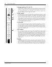
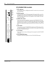
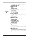
GROUP module
1
TO ST switch
This sends the GROUP signal to the stereo bus.
2
PAN control
This adjusts the panning of the signal sent to the stereo bus.
3
ON switch
This switch turns the GROUP on/off. The group is on when the switch is
pressed in. When off, no signal will be output from the corresponding
GROUP OUT jack.
4
AFL (After Fader Listen) switch
This monitors the GROUP signal. This is on when the switch is pressed in.
5
Group fader
This fader adjusts the signal level of the GROUP output.
∞
40
30
15
10
5
0
5
10
20
ON
AFL
PEAK
0
–20
1
4
5
2
3
∞
40
30
25
20
15
10
5
0
5
10
PAN
LR
ON
AFL
TO ST
1
2
3
4
5