


Rear panel 13
MX400 User’s Guide
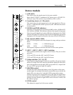
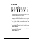
B ST INPUT 3/4 jacks
These are unbalanced 1/4” phone jacks which input a stereo source.
• Nominal input level: +4dB or –10dB
C AUX SEND jacks (+4dB)
These are unbalanced 1/4” phone jacks which output the signals of the AUX
SEND buses.
• Nominal output level: +4dB
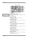
D GROUP INSERT I/O jacks (0dB)
These are 1/4” phone jacks patched in front of the GROUP faders. These
TRS jacks are unbalanced.
• Nominal output level: 0dB
• Nominal input level: 0dB
Tip=out, Ring=in, Sleeve=ground
E ST INSERT I/O jacks (0dB)
These are 1/4” phone jacks patched in front of the L-ST1-R fader of the mas-
ter module. These TRS jacks are unbalanced, with Tip=out, Ring=in, and
Sleeve=ground.
• Nominal output level: 0dB
• Nominal input level: 0dB
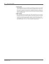
F GROUP OUT jacks (+4dB)
These are unbalanced 1/4” jacks which output the signals of the GROUP
buses.
• Nominal output level: +4dB
G ST2/MONI OUT jacks (+4dB)
These are unbalanced 1/4” jacks which output the signal of the STEREO L,R
bus or the signal of the MONITOR bus.
• Nominal output level: +4dB
H ST1 OUT jacks (+4dB)
These are balanced XLR3-32 type jacks which output the signal of the stereo
L,R bus.
• Nominal output level: +4dB
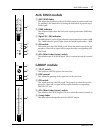
I POWER switch
This switch turns the power on/off. When in the “ON” position, the POWER
indicator will light.
J PHANTOM power switch
This switch turns the internal phantom power supply on/off. When in the
“ON” position, the PHANTOM indicator will light, and 48 DC power will
be provided between pin 2 and pin 3 of the INPUT A jacks.
If you do not need phantom power, be sure to turn this to the “OFF” posi-
tion.