


Master module (L-ST1-R) 9
MX400 User’s Guide
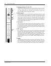
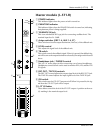
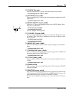
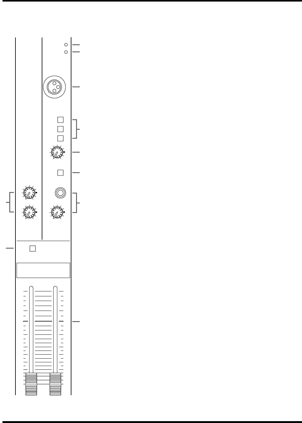
Master module (L-ST1-R)
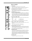
1 POWER indicator
This indicator lights when the power switch is turned on.
2 PHANTOM indicator
This indicator lights when the PHANTOM switch is turned on, indicating
that phantom power is being supplied.
3 TALKBACK IN jack
This is an unbalanced XLR type jack for connecting a talkback mic. The
nominal input level is –50dB.
4 Assign switches (GRP 1-4, AUX 1-4, ST)
These switches select the output destination (mix bus) of the talkback mic.
5 LEVEL control
This adjusts the signal level of the talkback mic.
6 TB switch
This switch controls the talkback signal. When it is pressed, the talkback sig-
nal will be sent to the output destination selected by the assign switch located
above.
7 Headphone jack / PHONES control
This is a 1/4” stereo phone jack for connecting a set of stereo headphones.
Headphones connected here can be used to monitor PFL, AFL, and the 2TR
IN signals.
8 REC OUT / TAPE IN controls
The REC OUT control adjusts the output signal level of the REC OUT jack.
The TAPE IN control adjusts the input signal level of the TAPE IN jack.
9 ON switch
This switch turns the ST1 OUT output on/off. When it is pressed in, the sig-
nal from the ST1 OUT jack will be output.
0 L-ST1-R faders
These faders control the level of the ST OUT output. A position at the zero
(0) marking is the nominal output level.
ON
L — ST 1 — R
∞
40
30
25
20
15
10
5
0
5
10
∞
40
30
25
20
15
10
5
0
5
10
REC OUT
010
TAPE IN
010
LEVEL
010
PHONES
010
TB
ST
AUX 1–4
GRP 1–4
TALKBACK IN
POWER
PHANTOM
1
2
5
6
0
3
4
7
8
9