


2
Front and rear panels
MX400 User’s Guide
Front and rear panels
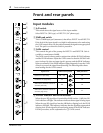
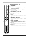
Input modules
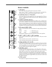
1
A/B switch
This switch selects the signal source of the input module.
Select INPUT A (XLR type) or INPUT B (1/4” phone type).
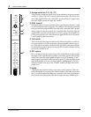
2
20dB pad switch
This is a 20dB input pad (attenuator) that affects INPUT A and INPUT B.
If the level of the input signal is too high for adjustments to be made using
the GAIN control alone, use the pad to attenuate the signal to an appropriate
level. The pad is on when this switch is pressed in.
3
GAIN control
This controls the gain of the preamp for INPUT A and INPUT B. Gain is
variable to a maximum of 44dB.
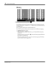
The GAIN control is always used in conjunction with the SIGNAL indicator
and the PEAK indicator. Adjust the GAIN control so that the SIGNAL indi-
cator is always lit when an input signal is present, and the PEAK indicator
lights occasionally. If the PEAK indicator lights frequently, lower the GAIN
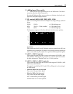
control to prevent the signal from distorting.The following table shows
usual settings for the GAIN control.
4
SIGNAL indicator and PEAK indicator
When the post EQ signal level (nominal level 0dB) reaches –10dB, the SIG-
NAL indicator will light. This indicator indicates that a signal is being input.
When the post EQ signal level reaches 3dB before clipping level, the PEAK
indicator will light. This indicator indicates that the signal has approached
clipping level. Set the signal level based on the status of the PEAK indicator.
For the procedure, see the explanation for
3
GAIN control.
Signal source GAIN control position 20dB pad switch
Dynamic mic (low level) –60 ~ –50 off
Condenser mic (high level) –35 off
Audio device, electronic musical in-
strument (low level)
–20 off
Audio device, electronic musical in-
strument (high level)
+4 on
A
B
20dB
GAIN
–16 –60
HIGH
–15 +15
MID FREQ
250 5K
MID
–15 +15
LOW
–15 +15
AUX 1
010
AUX 2
010
AUX 3
010
AUX 4
010
AUX 5
010
P
O
S
T
P
R
E
PRE
EQ
80
PEAK
SIGNAL
1
2
3
5
6
4
7
8
–16
–60
GAIN
–16
–60
GAIN
–16
–60
GAIN
–16
–60
GAIN