6
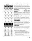
Digital Effects Processor - General
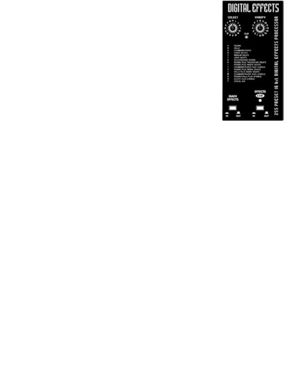
The internal Digital Effects Processor is a full 16-bit,
20kHz bandwidth DSP-based effects subsystem devel-
oped by Applied Research & Technology in Rochester,
New York. It has been custom programmed with 255
effects ranging from reverb to echo and special effects.
The selection of effects was determined in collaboration
with a panel of sound engineers experienced in live per-
formance mixing. As a result you should find the internal
effects system to be more than adequate for most applica-
tions.
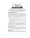
Main Effects In/Out Button
The In/Out button allows you to switch the preset effects
on or off. You might, for example, choose to have a par-
ticular special effect on your voice at certain times. The In/
Out button would let you punch it in and out as required.
Digital Effects Clip LED
The Clip LED helps you to set up channel EFX send levels
for optimum signal strength to drive the effects processor.
With signals going into the channels requiring effects,
and with their level faders pushed up half-way or farther (remember, the EFX sends are
post-fader), simply increase the EFX send control levels on those channels until some
Digital Effects Clip LED activity is observed. Then turn EFX send levels down slightly
until the flashing stops.
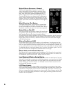
Effects Cue Button & LED
This feature allows you to preview effects via headphones. First, depress the Cue
button - the LED will illuminate to indicate CUE “on”. Now, with the desired chan-
nel’s EFX send controls turned up roughly half-way, the Headphone Crossfader set
to Cue and the Phones level control turned up, Select and Modify the desired effect.
To add that effect to your main program mix, press the Cue button again (Cue LED
goes off) and slide the Headphone Crossfader from Cue to Pgm.
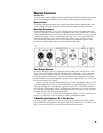
Phones Jack, Level Control & Sources
The Phones jack accepts standard stereo headphones. The Phones level control and
Phones jack are located in the lower right area of the control panel. The sources for
all headphone signals are the Mains (or Pgm) and Cue buses.
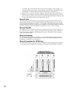
Level Displays & Display Assign Button
These displays follow either the Left and Right stereo main mix activities or Cue (any-
thing on Cue) and Pgm (a mono mix of the main program), as selected by the Display
Assign button. If either or both of the red Clip lights at the right end of the level dis-
play is flashing too much of the time in L/R mode, lower the Mains master level to
avoid possible distortion on peaks.
L & R Amp In Jacks
These are switching jacks, which enable you to directly access either or both chan-
nels of the built-in power amplifier while disconnecting them from their normal inter-
nal functions. This permits you to insert an external EQ, a processor /crossover (e.g.
élite) or a compressor/limiter between the mixer section’s Main Outputs and the Amp
In jacks. This in-series patch provides the 100% signal processing essential for these
functions to work properly.


