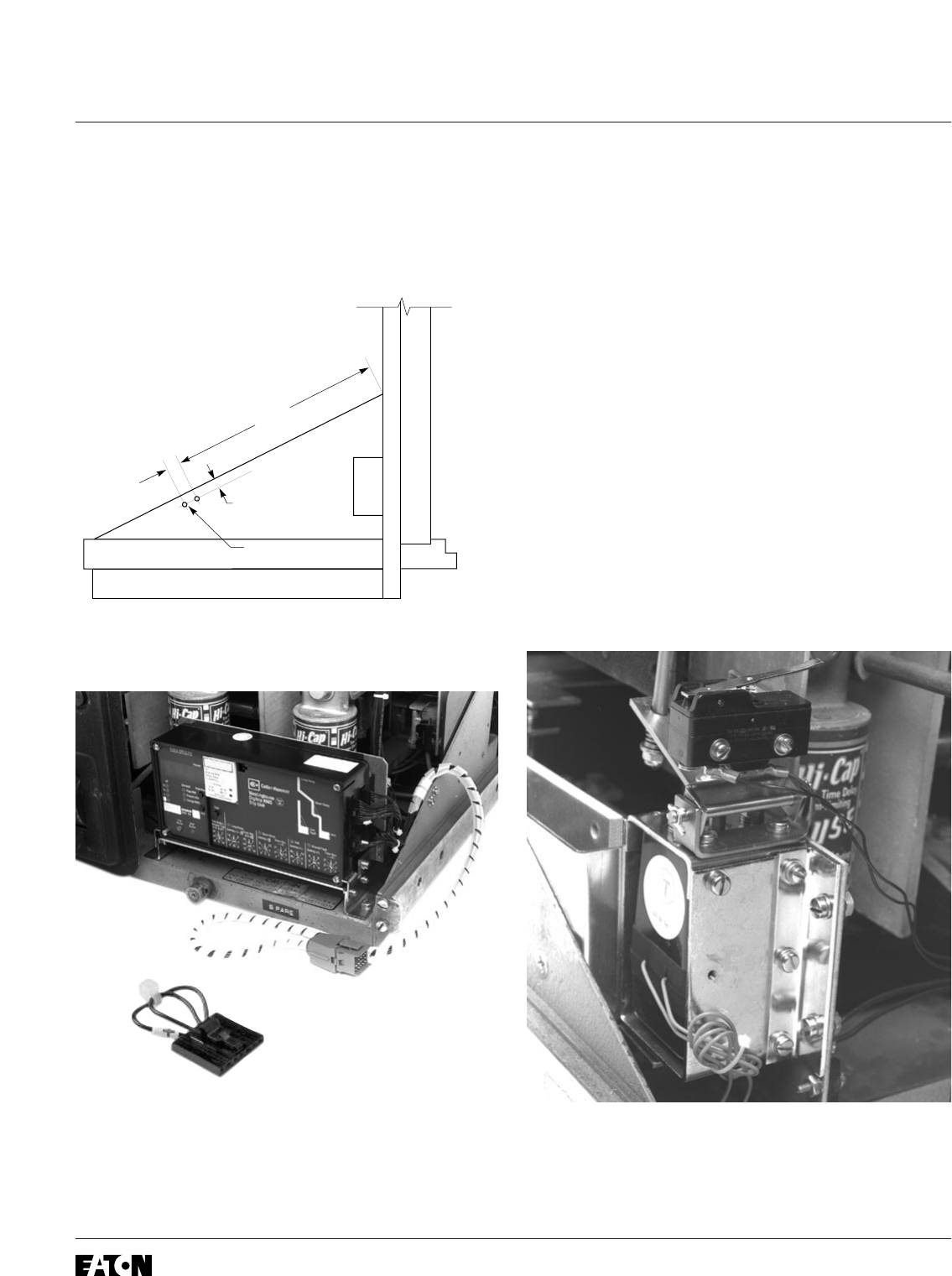
Step 14: Installing the External Harness
A.
For all RMS/R Kits except the 510 Basic
.
Using Drilling Plan “D”, drill two .190" holes
in the right Breaker Side Plate.
B. Connect the External Harness to the Trip Unit.
NOTE: For RMS/R 510 Basic Kits, the External
Harness is the plug pictured above. It is to be
plugged into the right side of the Trip Unit.
C. Using the two (2) nylon wire clamps,
.164-32 × .500" screws, flat washers, lock
washers, and nuts provided, attach the
External Harness to the right Breaker Side
Plate as shown.
D.
For Kits Supplied with a PT Module Only.
Connect the PT Extension Harness to the
External Harness. Fold any excess length of
the PT Extension Harness and secure using
the nylon wire ties provided. The excess
should be tucked in against the right Breaker
side panel.
E.
For Kits Supplied with an Aux. Switch Only
.
Route the two wires (with ring terminals) from
the External Harness behind the Trip Unit and
along the bottom of the Breaker to the Aux.
Switch Assembly. Connect one wire to the
normally “Closed” terminal and the other wire
to the “Common” terminal of the Microswitch.
F. Use the nylon wire ties provided to dress all
wiring to keep it away from any moving parts
within the Breaker.
Effective December, 1998
IL 33-FC6-1
Page 12