Effective March, 1998
IL 33-A1C-1
Page 9
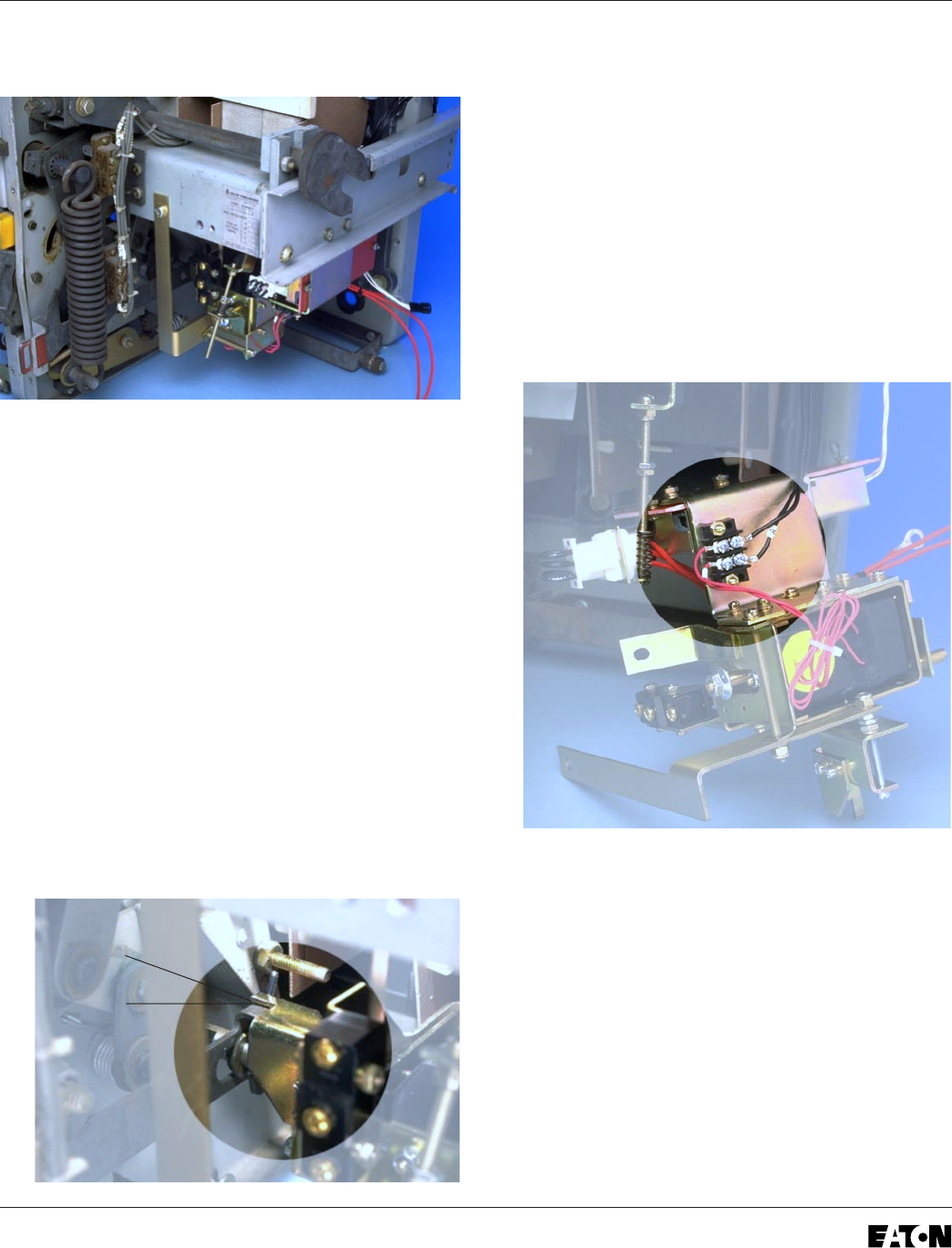
Step 8: Installing the DTA Assembly
A. Temporarily mount the DTA Assembly to the
right Breaker Frame using the existing holes
and the (2) .250-20 × .750" bolts, (4) flat
washers, (2) lock washers, and (2) nuts
supplied.
Note: Do not tighten the hardware securing
the DTA to the Breaker Frame at this time.
B. The mounting bracket used to secure the DTA
Assembly to the front of the Breaker will be
used to achieve a gap between the Trip Finger
and Breaker Push-to-Trip Mechanism Arm.
Move the DTA Assembly up or down until a gap
of approximately .06" to .09" has been
achieved. Using the center of the slot in the
mounting bracket as a guide, mark the front
Breaker Frame at the correct location where the
hole must be drilled.
C. Remove the DTA Assembly. Using a .266" drill,
drill a hole in the front Breaker Frame in the
location marked in Step 8b.
Note: Cover the region below the area to be
drilled to prevent metal shavings from
falling into the Breaker Mechanism.
D. With the DTA Assembly setting in front of the
Breaker, connect the wire from the DTA
Extension Harness marked with the “+” to the
“+” terminal and the unmarked wire to the other
terminal on the 2-Point Terminal Block.
E.
For Kits Supplied with a PT Module Only.
Refer to Section 7-3, Power Flow Convention of
the Retrofit Application Data, supplied with the
Retrofit Kit for additional wiring information and
to verify the Phase Convention used on this
Breaker Application.
GAP


