Effective March, 1998
IL 33-A1C-1
Page 14
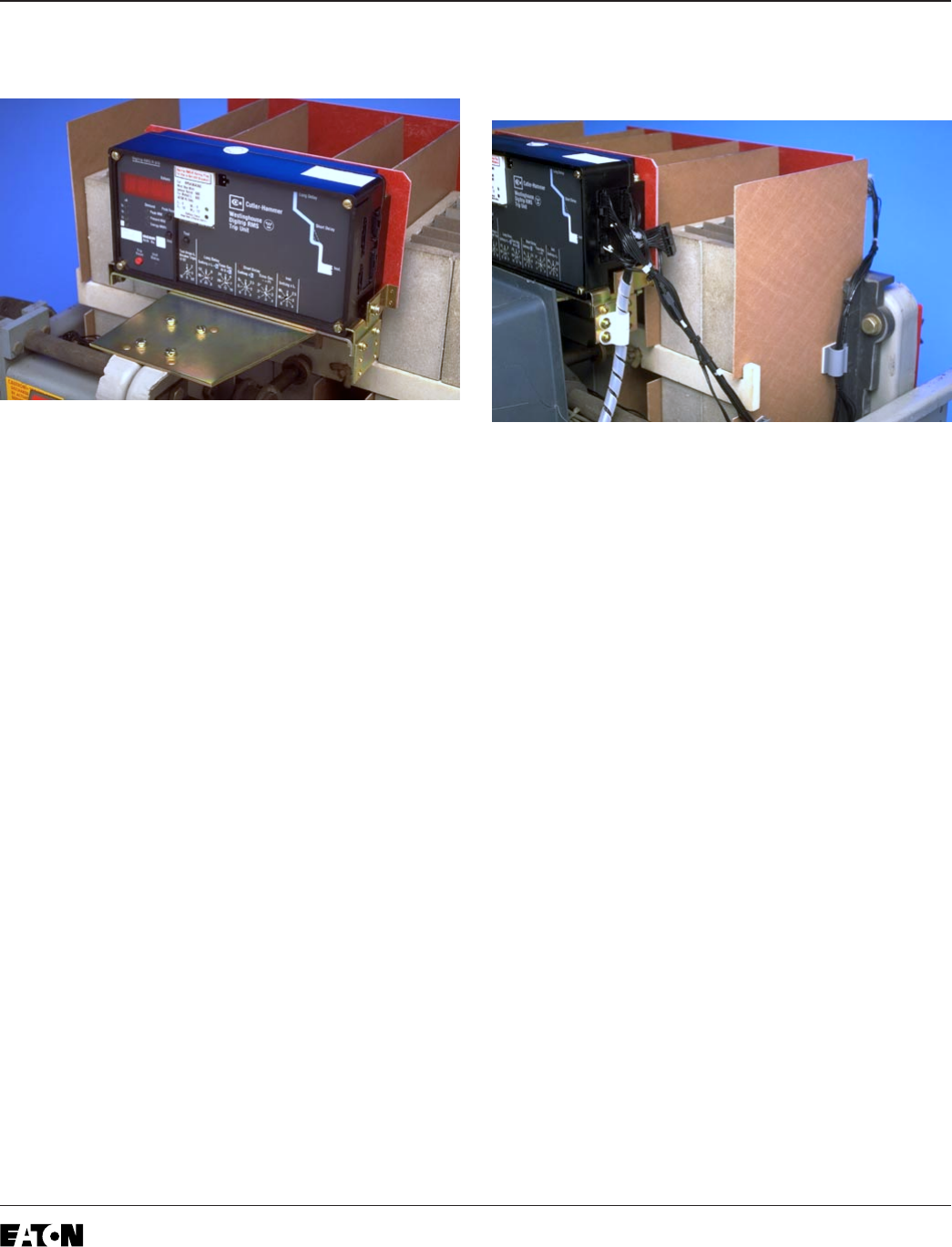
Step 12: Installing the Trip Unit Assembly
A. Mount the Trip Unit Assembly on top of the
Breaker Mechanism, as shown, using the holes
drilled in Step 3b and the (4) .190-32 × .500"
screws, (8) flat washers, (4) lock washers, and
(4) nuts supplied.
B. Remove the Trip Unit Cover and install the
Rating Plug. Replace the cover.
C. Install the Digitrip Nameplate to the top of the
Trip Unit.
Step 13: Final Connection of the Harnesses
and Wiring
Note: The power convention of the Allis
Chalmers LA-1600 Blue Series Breakers is
normally
Top to Bottom
, meaning the Top
Breaker Phase Frames are on the
Line Side
of
the Breaker and the Bottom Breaker Stabs are
on the
Load Side
.
The HV Wires from the CPT MUST BE
ATTACHED to the
Line Side
of the Breaker. If it
is determined that the power flow for the
Breaker application is opposite the normal
convention, the HV Wires must be attached to
the Bottom Breaker Studs.
Looking into the Breaker from the front,
the right hex bolt on the Phase 1 and 2 or
Phase 2 and 3 Bottom Breaker Studs can
be used to mount the HV Wires.
Note: The Line Side HV Wires are longer that
necessary and are cut during the following
steps. Before cutting the wires, be sure that
sufficient length is left so that the connections
can be made to the correct Finger Clusters or
Phase Frames.


