I/O Module Installation and Wiring - I/O Terminal Block Wiring Diagrams
82 HC900 Hybrid Controller Installation and User Guide Revision 5
9/03
Relay Output Module Wiring
The Relay Output Module provides eight individually isolated, electromechanical relay outputs. Four of
the outputs are Form-C, and the other four are Form-A. A schematic showing the relationship of individual
Form-A relays and Form-C relays to external (user) connections is given in Figure 47.
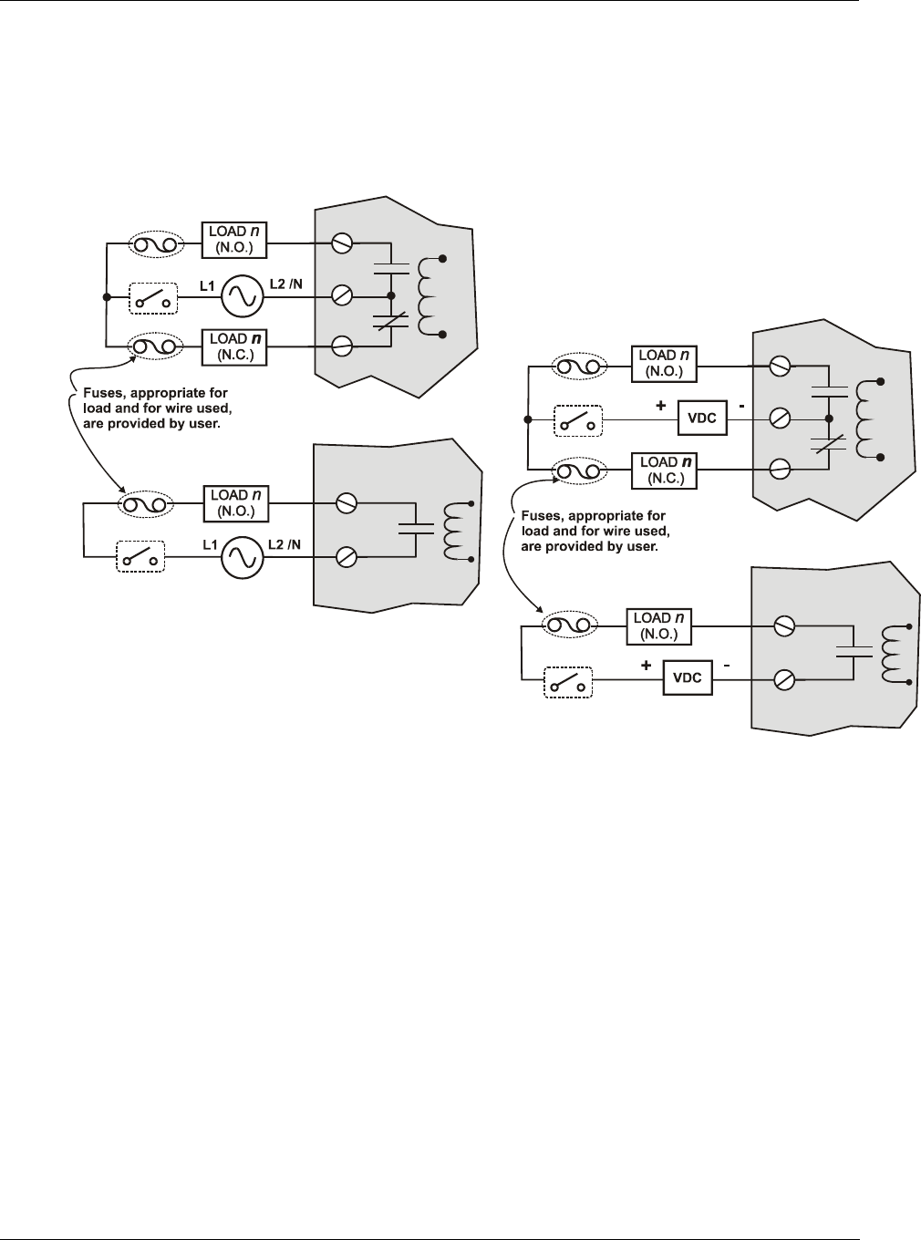
Examples of Relay Output wiring as they relate to connections on the Terminal Block are shown in Figure
48.
Figure 47 - Schematic Example: Relay Output and External Wiring
Contact Rating
Maximum current/output: 4A at 250Vac/30Vdc with resistive load
Maximum current per module: No de-rating per module, but ensure compliance with maximum ratings
for each output.
Required Output Fusing
Outputs are not fused in the Relay module. Install a fuse for each output at the field device that is
appropriate for the load and the wire used.
Jumper Comb
A ten-position jumper comb, available for the AC Output Module, can be cut in half and used as shown in
Figure 49 to reduce the number of wires required to connect the Relay Output Module to AC Neutral or to
DC Common.


