46
INSTALLATION AND WIRING
2.3.7 Instructions for compliance with U.S. and Canadian Electrical
Codes
(Standard to comply with: UL 508C)
(1) Installation
The FR-A500 is UL-listed as a product for use in an enclosure.
Design an enclosure so that the ambient temperature, humidity and ambience of the inverter will satisfy the
specifications. (Refer to page 223.)
(2) About wiring protection
When installing the inverter in the United States of America, protect its branch cables in accordance with the
National Electrical Code and local standards.
When installing the inverter in Canada, protect its branch cables in accordance with the National Electrical
Code and the corresponding State Standards.
(3) Short circuit ratings
200V class
Suitable For Use in A Circuit Capable of Delivering Not More Than 5 or 10kA rms Symmetrical Amperes, 230
or 500 Volts Maximum.
400V class
Suitable For Use in A Circuit Capable of Delivering Not More Than 10kA rms Symmetrical Amperes, 500
Volts Maximum.
(4) Wiring of the power supply and motor
For wiring the input (R, S, T) and output (U, V, W) terminals of the inverter, use the UL-recognized copper
wires (rated at 75°C) and round crimping terminals. To crimp the crimping terminals, use the crimping tool
recommended by the terminal maker.
(5) Motor overload protection
When using the electronic overcurrent protection function as motor overload protection, set the rated motor
current in Pr. 9 "electronic thermal O/L relay".
When connecting two or more motors to the inverter, install external thermal relays for individual motors.
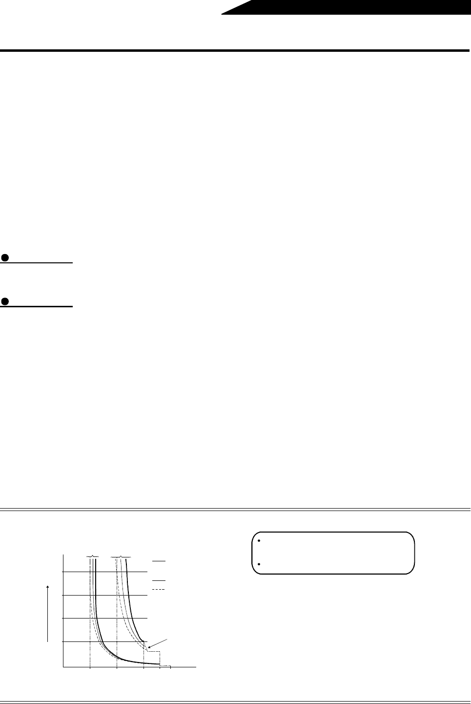
Reference: Motor overload protection characteristics
0 50 100 150 180200
240
180
120
60
Operation time (s)
50% setting
(Note 1, 2)
100% setting
(Note 2)
(Note 1) When you set the 50% value (current
value) of the rated inverter output current.
(Note 2) The % value denotes the percentage of
the current value to the rated inverter
output current, not to the rated motor current.
(Note 3) This characteristic curve will be described
even under operation of 6Hz or higher
when you set the electronic overcurrent
protection dedicated to the Mitsubishi
constant-torque motor.
30Hz or higher
(Note 3)
Inverter output current (%)
(% to rated inverter output current)
Electronic overcurrent
protection for transistor
protection
20Hz
10Hz
Protection activating range
Range on the right of characteristic curve
Normal operating range
Range on the left of characteristic curve


