10
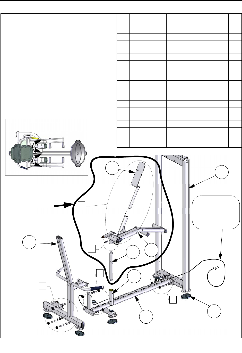
1. Position the main frame and upright
frame. Route the cable before assembling
the two components as shown.
2. Loosely assemble the main frame and
upright hardware.
3. Pre-assemble the right arm and axle as
shown. Tap the pins into position with a
hammer.
4. Assemble the thigh pad plate. Tap the pin
into position with a hammer.
5. Assemble the arm to the frame as shown.
6. After aligning all component edges and
surfaces, tighten ALL the hardware.
STEP 1: ASSEMBLE THE FRAME COMPONENTS
&
%
$
)
'
19
17
16
15
9
18
13
14
Make sure the thigh pads
can be rotated as shown.
A
B
D
F
C
ITEM PART NO.DESCRIPTION QTY.
1 C 445 SCREW, 3/8”-16 X 1” 3
2 C 450 SCREW, 3/8”-16 X 2-1/2” 2
3 C 749 LOCKWASHER, 3/8” 4
4 C 449 SCREW, 3/8”-16 X 2-1/4” 1
5 C 754C FLAT WASHER, 3/8” 8
6 C 766A LOCK NUT, 3/8”-16 2
7 C 955A BOLT COVER, BASE 8
8 C 955S BOLT COVER, SILVER 8
9 S 550 MOLDED RUBBER FEET 7
10 FS-CLR-002 COLLAR, 25.4MM 1
11 FS-PIN-100 ROLL PIN, 8mm X 35mm 1
12 FS-PIN-200 ROLL PIN, 10mm X 45mm 2
13 FS52-UPR-000X UPRIGHT FRAME 1
14 FS52-MFR-000X MAIN FRAME 1
15 FS52-MFR-100X MAIN FRAME, REAR 1
16 FS52-MFR-300X THIGH PAD PLATES 1
17 FS52-MFR-400X SLEEVE, AXLE SPACER 1
18 FS52-ARM-100X RIGHT ARM 1
19 FS52-AXL-000X AXLE, RIGHT ARM 1
TOP VIEW
PRE-ASSEMBLE
BEFORE INSERTING
INTO MAIN FRAME
Route the cable
before assembling
the frame.
(FS52-CBL-200X)


