12
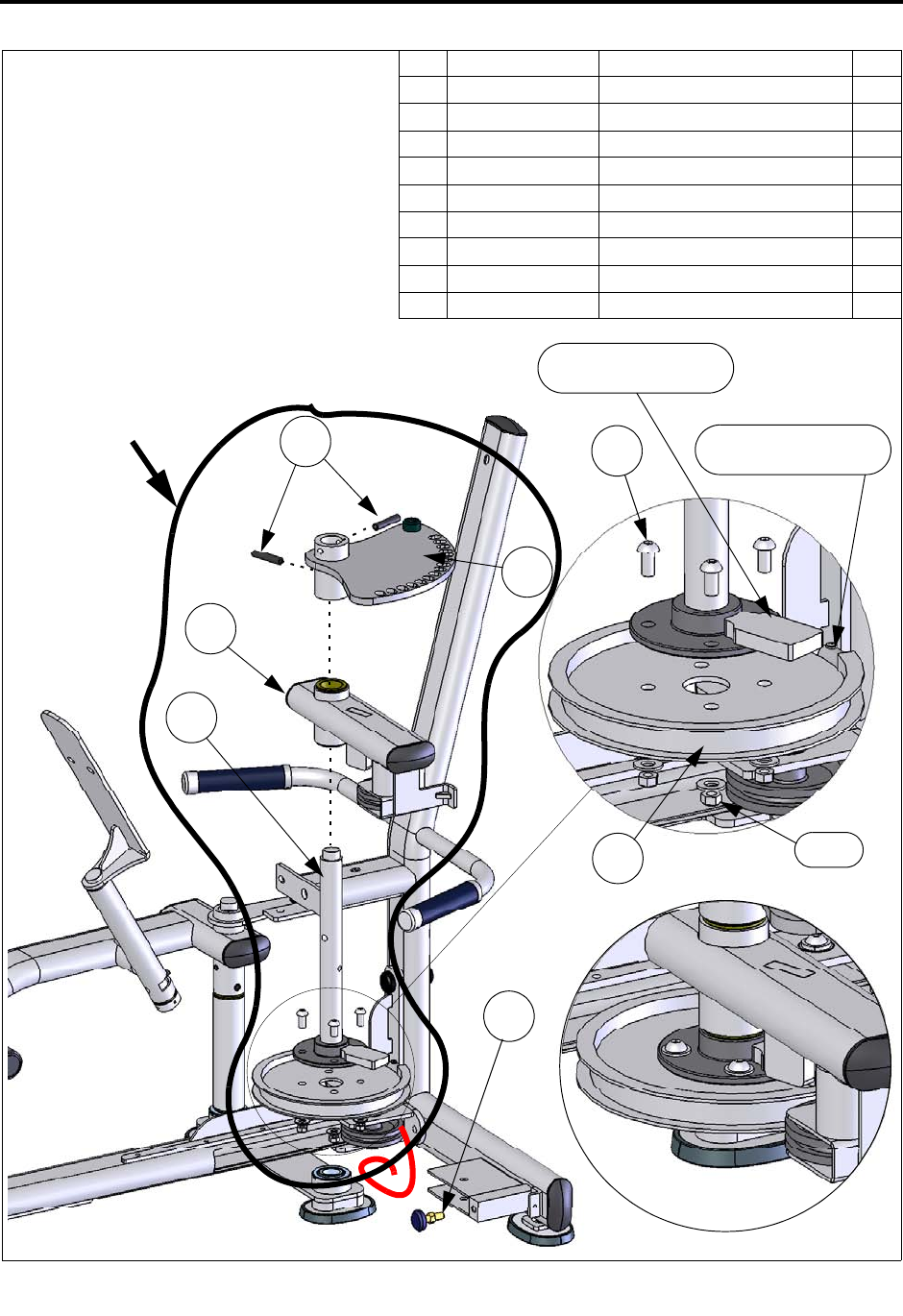
STEP 2: ASSEMBLE THE ADJUSTMENT PLATE
ITEM PART NO.DESCRIPTION QTY.
1 C 754C FLAT WASHER, 3/8” 4
2 C 766A LOCK NUT, 3/8”-16 4
3 C 911 SCREW, 3/8”-16 X 3/4”, BHCS 4
4 FS52-ADJ-100X ADJUSTMENT PLATE 1
5 FS52-ARM-200X PULLEY ARM 1
6 FS52-AXL-100X AXLE, LEFT ARM 1
7 FS52-CAM-000X CAM 1
8 FS-PIN-300 ROLL PIN, 10mm X 50mm 2
9 FS-STP-001 BUMPER STOP 1
2, 1
7
8
5
6
4
CAM/CABLE
CONNECTION HERE
X4
X4
3
9
STOP WILL BE
ADJUSTED LATER
PRE-ASSEMBLE
BEFORE INSERTING
INTO MAIN
(ASSEMBLED)
FRAME
1. Assemble the cam to the axle and
tighten the hardware. The cam can
only be assemble to the axle in one
orientation.
2. Pre-assemble the axle, the Pulley
Arm and the adjustment plate.
Make to sure orient the adjustment
plate as shown and then install the
roll pins using a hammer.
3. Insert the axle into the bearing in
the main frame.
NOTE ORIENTATION
OF AXLE


