


2 Description
WMS 40 SINGLE/DUAL
24
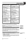
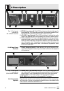
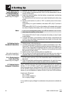
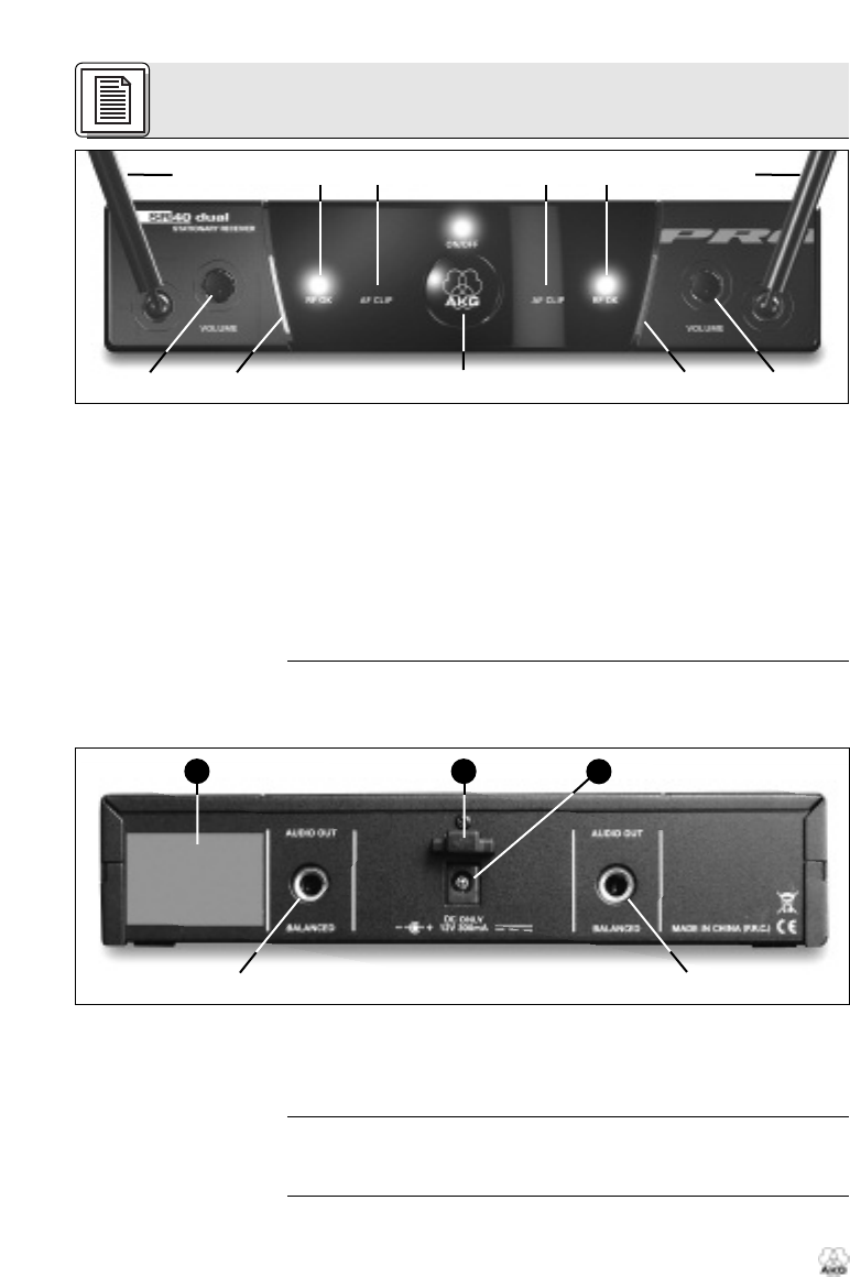
Fig. 1: Front panel
controls on
SR 40 DUAL receiver
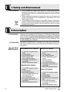
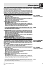
2.4.2 Rear Panel
Controls
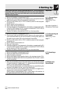
Fig. 2: Rear panel
controls on
SR 40 DUAL receiver.
2.4.3 Automatic
Squelch
4 RF OK (1 per channel): This LED illuminates to indicate that signal is
being received. If no signal is received or the automatic squelch is on,
the RF OK LED goes out and the audio output is muted.
5 AF CLIP (1 per channel): This LED illuminates to indicate the audio
level of the received signal is overloading the receiver's audio section.
6 Color code lines: The color indicates the carrier frequency of the re-
spective receiver channel. Both the SR 40 SINGLE and the SR 40 DUAL
have two color code lines. On the SR 40 SINGLE, both color code lines
are of the same color. Transmitters tuned to the same frequency are
marked with the same color. Refer to the Manual Supplement sheet
for a color code table.
7 Carrier frequency label: A label indicating the carrier frequency (fre-
quencies) and approval marks of your receiver is affixed to the rear panel
of the receiver.
8 AUDIO OUT (1 per channel): Balanced TRS 1/4" jack, adjustable from
mic to line level. You can connect the output either to an XLR micro-
phone input or to an unbalanced line input on a mixer or amplifier.
9
Strain r
elief
for the feeder cable of the supplied AC adapter
.
10
DC ONL
Y:
Input connector for the supplied AC adapter
.
The automatic squelch cir
cuit switches the r
eceiver of
f if the r
eceived sig-
nal is too weak, in or
der to suppr
ess the r
elated noise or the r
esidual noise
of the r
eceiver while the transmitter is of
f.
ᕢᕢ
ᕡᕣ ᕦ ᕣᕦ
ᕤ ᕤᕥᕥ
7 9
10
ᕨ
ᕨ