


3 Setting Up
29WMS 40 SINGLE/DUAL
Important
3.7.1 Connecting a
Microphone
Refer to fig. 10 on
page 3.
Also refer to section 4
Microphone Technique.
3.7.2 Connecting an
Instrument
Refer to fig. 10 on
page 3.
3.7.3 Inserting a
Label
3.8 Before the
Soundcheck
Please note that AKG cannot guarantee that the PT 40 PRO bodypack
transmitter will work perfectly with products from other manufacturers
and any damage that may result from such use is not covered by the
AKG warranty scheme.
1. Remove the battery compartment lid (21).
2. Plug the mini XLR connector on the cable of your microphone into the
audio input socket (18) on the bodypack transmitter.
3. Set the on/off switch (16) to "ON" to switch power to the bodypack
transmitter on.
4. Switch power to the receiver on.
5. Talk or sing into the microphone.
6. Use the screwdriver (21a) integrated in the battery compartment lid (21)
to set the GAIN control (22) to a position where the AF CLIP LED (5)
on the receiver will flash occasionally.
7. Replace the battery compartment lid (21) on the transmitter.
1. Remove the battery compartment lid (21).
2. Plug the jack plug on the MKG L guitar cable into the output jack on
your instrument and the mini XLR connector on the guitar cable into
the audio input socket (18) on the bodypack transmitter.
3. Set the on/off switch (16) to "ON" to switch power to the bodypack
transmitter on.
4. Switch power to the receiver on.
5. Play your instrument.
6. Use the screwdriver (21a) integrated in the battery compartment lid (21)
to set the GAIN control (22) to a position where the AF CLIP LED (5)
on the receiver will flash occasionally.
7. Replace the battery compartment lid (21) on the transmitter.
1. Remove the battery compartment lid (21).
2. Remove a label from the supplied sheet.
3. Letter the label as desired.
4. Remove the battery and place the label on the viewing window (21b).
5. Replace the battery and slide the compartment lid (21) back in place
on the transmitter.
1. Move the transmitter around the area where you will use the system
to check the area for "dead spots", i.e., places where the field strength
seems to drop and reception deteriorates.
If you find any dead spots, try to eliminate them by repositioning the
receiver. If this does not help, avoid the dead spots.
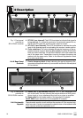
2. The RF OK LED (4) on the receiver going out means no signal is be-
ing received or the automatic squelch is active.
Switch power to the transmitter ON or move closer to the receiver, to
the point that the RF OK LED (4) will come back on.