


1. Introduction
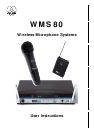
Thank you for selecting the WMS 80 wireless microphone system
from AKG. Please take the time to read through this Manual. It
contains information on how to make optimum use of your equip-
ment. Have fun!
2. Precautions
2.1.Spill no liquids on the equipment and do not drop any objects
through the ventilation slots in the equipment.
2.2.Do not place the equipment near heat sources such as radia-
tors, heating ducts, or amplifiers, etc. and do not expose it to
direct sunlight, excessive dust, moisture, rain, mechanical
vibrations, or shock.
2.3.Be sure to dispose of used batteries as required by local
waste disposal rules. Never throw batteries into a fire (risk of
explosion).
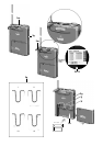
3. The WMS 80 Systems
Two different WMS 80 Systems are available:
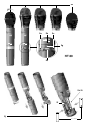
3.1. Handheld System
1 SR 80 Receiver
1 AC power adapter for 11.7 VAC
1 RMU 80 19” rack mounting kit for 2 SR 80 receivers
1 BP 80 blank panel
1 screwdriver
1 HT 80 Handheld Transmitter
2 AA size 1.5 V dry batteries
1 SA 43 stand adapter
1 adjustable protective ring for controls
3.2. Bodypack System
1 SR 80 Receiver
1 AC power adapter for 11.7 VAC
1 RMU 80 19” rack mounting kit for 2 SR 80 receivers
1 BP 80 blank panel
1 screwdriver
1 PT 80 Bodypack Transmitter
1 belt clip
2 AA size 1.5 V dry batteries
Check that the package contains all the parts listed above for your
system. If anything is missing, please contact your AKG dealer.
3.3. Optional Accessories
CH 60/80 plastic carrying case for one complete WMS 80
system.
Color Coding Kit: Set of rings (for the HT 80) and platelets
(for SR 80 and PT 80) in various colors for identifying the indi-
vidual channels of a multichannel system.
4. SR 80 Receiver
The SR 80 is a stationary True Microcontrolled Diversity receiver
for use with WMS 80 transmitters. The SR 80 operates in a sub-
band up to 4 MHz wide of the 710 MHz to 861 MHz UHF
carrier frequency range. The SR 80 can be switched to a maxi-
mum of 15 different carrier frequencies depending on local fre-
quency allocations.
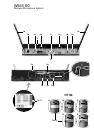
4.1. Controls
4.1.1. Front Panel
The lettering of the front panel controls is protected against scratch-
ing by a protective film. To remove the film, just peel it off.
1a POWER: Switches the power to the SR 80 ON and OFF.
1b VOLUME: The VOLUME pot matches the SR 80’s output level
to the input sensitivity of your mixer or amplifier.
1c SQUELCH: The squelch circuit switches the receiver off if the
received signal is too weak, in order to suppress the related
noise or the residual noise of the receiver while the transmitter
is off. Set the SQUELCH control to minimum before first switch-
ing the receiver on. (For details, refer to section 9.)
1d CHANNEL: This rotary switch selects the desired carrier fre-
quency or its alternative frequencies.
1e Telescoping antennas: The SR 80 is a diversity receiver and
uses two antennas in order to receive the transmitter signal at
two different spots. The diversity electronics will automatically
activate the antenna that delivers the better signal.
1f MUTE LED: Lights red if the squelch is active. In this case the
audio output will be muted. Note that the MUTE LED does
not indicate the position of the MUTE switch on the trans-
mitter!
1g RF LOW/OK LEDs: Indicate the received field strength of the
transmitter signal.
FCC Statement
This equipment has been tested and found to comply with the limits for a Class B digital device, pursuant to Parts 74, 15, and 90 of the
FCC Rules. These limits are designed to provide reasonable protection against harmful interference in a residential installation. This equip-
ment generates, uses, and can radiate radio frequency energy and, if not installed and used in accordance with the instructions, may
cause harmful interference to radio communications. However, there is no guarantee that interference will not occur in a particular instal-
lation. If this equipment does cause harmful interference to radio or television reception, which can be determined by turning the equip-
ment off and on, the user is encouraged to try to correct the interference by one or more of the following measures:
• Reorient or relocate the receiving antenna.
• Increase the separation between the equipment and the receiver.
• Connect the equipment into an outlet on a circuit different from that to which the receiver is connected.
• Consult the dealer or an experienced radio/TV technician for help.
Shielded cables and I/O cords must be used for this equipment to comply with the relevant FCC regulations.
Changes or modifications not expressly approved in writing by AKG Acoustics may void the user’s authority to operate this equipment.
This device complies with Part 15 of the FCC Rules. Operation is subject to the following two conditions: (1) this device may not cause harm-
ful interf e rence, and (2) this device must accept any interf e rence received, including interf e rence that may cause undesired operation.