


1h AF/PEAK LEDs: Indicate the received audio level.
The green LED lighting and the red LED flashing occasionally
indicate optimum modulation.
If the LEDs do not light, the sensitivity setting on the transmitter
is too low.
The red LED lighting constantly indicates overmodulation.
1i Diversity LEDs A and B: Indicate which of the two receiving
antennas is active.
1j Color Code: If you use the receiver within a multichannel
system, you may remove the black plastic platelet and re-
place it with a colored platelet included in the optional Color
Coding Kit to identify each channel by a different color.
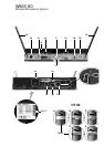
4.1.2. Rear Panel
1k Carrier Frequency Table: A label listing the available fre-
quencies is affixed to the bottom panel of the receiver.
1l Frequency Set Designation: The label on the bottom panel
also indicates the designation of the Frequency Set.
1m POWER: Input connector for the supplied AC adapter.
1n AUDIO OUT UNBALANCED: Unbalanced audio output on a
1/4” mono jack for connecting to, e.g., a guitar amplifier.
1o AUDIO OUT BALANCED: Balanced 3-pin XLR audio output
for connecting to, e.g., a microphone input on the mixing
console.
1p BALANCED LINE/MIC: Switches the balanced audio output
to line or microphone level. Therefore, you can connect the
SR 80 to microphone or line level inputs as desired.
1q Screwdriver for adjusting the CHANNEL and GAIN controls
on the transmitters.
4.2. Optional Accessories
Color Coding Kit
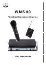
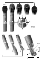
5. HT 80 Handheld Transmitter
The HT 80 handheld transmitter and matching microphone ele-
ments (optional) provide the same acoustic performance as the
equivalent hardwire microphone versions. The microphone ele-
ments available for the HT 80 have been specifically designed for
vocal use.
The HT 80 operates in a subband up to 4 MHz wide within the
710 MHz to 861 MHz UHF carrier frequency range. The HT 80
can be switched to a maximum of 15 different carrier frequencies
depending on local frequency allocations.
The transmitter uses a dipole antenna integrated in the body.
The controls can be protected against accidental misadjustment
collectively (2d) or individually with the supplied adjustable pro-
tective ring (2j).
5.1. HT 80 Controls
2a PWR: Switches the transmitter power ON (“I”) and OFF (“0”).
2b Status LED: Indicates battery status and audio input overload.
LED glowing dimly: batteries are OK.
LED constantly lighting brightly: batteries will be dead in
about 90 minutes.
LED illuminating brightly: audio input is overloaded.
2c MIC: Mutes the audio signal (position “0”) while power and
carrier frequency remain ON. Thus, no noise will become
audible if you mute the microphone, even if the SQUELCH
control (1c) on the receiver is set to minimum.
2d Color Code: If you use the transmitter in a multichannel system
you can remove the black plastic ring and replace it with a
colored ring from the optional Color Coding kit to identify
each wireless channel by a different color.
2e GAIN: This rotary pot allows you to match the microphone
level to the transmitter’s audio section.
2f Battery Compartment: Refer to Section 9. Setting Up.
2g CHANNEL: This rotary switch selects the desired carrier fre-
quency (depending on local allocations) or switches between
the carrier frequency and its alternative frequencies.
Important: Prior to selecting frequencies, switch the transmitter
OFF.
2h Carrier Frequency Table: A label listing the available fre-
quencies is affixed to the battery compartment.
2i Frequency Set Designation: The label inside the battery com-
partment also indicates the designation of the Frequency Set.
2j Adjustable protective ring: Protects the controls from being
misadjusted accidentally.
5.2. Interchangeable Microphone Elements
The interchangeable microphone elements (2k) D 880 WL1,
D 3700 WL1, D 3800 WL1, C 5900 WL1, and C 535 WL1
are acoustically and mechanically identical to the equivalent hard-
wire versions. They feature the same transducer capsules and
mechanical construction.
Extremely high gain before feedback, optimum handling noise
rejection, ultimate protection from damage, and an integrated
wind and pop screen are only the most impressive features of
these microphones. For more details, refer to the respective AKG
brochures.
5.3. Optional Accessories
W 880 foam windscreen for D 880 WL1
W 3001 foam windscreen for D 3700 WL1 and
C 5900 WL1
W 23 foam windscreen for C 535 WL1
Color Coding Kit
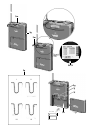
6. PT 80 Bodypack Transmitter
You can use the PT 80 bodypack transmitter with both dynamic
microphones and condenser microphones operating on a supply
voltage of approx. 7 V. You may also connect an electric guitar,
electric bass, or remote keyboard.
The PT 80 operates in a subband up to 4 MHz wide of the
710 MHz to 861 MHz UHF carrier frequency range. The HT 80
can be switched to a maximum of 15 different carrier frequencies
depending on local frequency allocations.
6.1. Controls
3a POWER: Switches the transmitter power ON (“I”) and OFF
(“0”).
3b MIC: Mutes the audio signal (position “0”) while power and
carrier frequency remain ON. Thus, no noise will become
audible if you mute the microphone even if the SQUELCH
control (1c) on the receiver is set to minimum.
3c Status LED: Indicates battery status and audio input overload.
LED glowing dimly: batteries are OK.
LED constantly lighting brightly: batteries will be dead in
about 90 minutes.
LED illuminating brightly: audio input is overloaded.
3d Audio Input: 3-pin mini XLR connector with both mic and line
level pins that automatically match the connector pinout of the
microphone or optional MKG/L guitar cable.
3e Color Code: If you use the transmitter within a multichannel
system, you may remove the black plastic platelet and re-
place it with a colored platelet included in the optional Color
Coding Kit to identify each channel by a different color.