


9.4.4. Connecting to Power
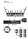
1. Unfold the two antennas (1e) and extend them fully to obtain
optimum reception.
2. Set the SQUELCH control (1c) fully CCW.
3. Check that the AC mains voltage stated on the sup-
plied AC adapter is identical to the AC mains volt-
age available where you will use your WMS 80.
Using the AC adapter with a different AC voltage may cause
irreparable damage to the unit.
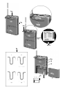
4. Plug the feeder cable on the supplied AC adapter into the
POWER socket (1m) on the receiver.
5. Bend part of the feeder cable into a bight, pass the bight
through the opening in the lower part of the screwdriver sup-
port, and place the end of the bight snugly against the strain
relief hook above the POWER socket (1m).
6. Plug the power cable on the supplied AC adapter into a con-
venient power outlet.
7. Switch the receiver ON with the POWER switch (1a).
Note: For easy channel identification in a multichannel setup, you
can replace the snap fitted color code platelet (1j) with a dif-
ferent-color platelet included in the optional Color Coding Kit.
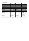
9.4.5. Antennas
For optimum reception, make sure to extend the two telescoping
antennas (1e) exactly as far as specified for each Frequency Set
in Table 1 on page 39.
9.5. System Adjustments
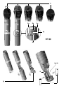
1. Handheld transmitter: Using the supplied screwdriver
(1q), set the GAIN control (2e) so that on the receiver the green
AF LED (1h) will light constantly and the red PEAK LED (1h) on
the receiver and the status LED (2b) on the transmitter will only
flash on the loudest signal peaks.
Bodypack transmitter: Using the supplied screwdriver
(1q), set the GAIN control (3j) so that the green AF LED (1h) on
the receiver will light constantly and the status LED (3c) on the
transmitter as well as the red PEAK LED (1h) on the receiver will
only flash on the loudest signal peaks.
2. The red PEAK LED (1h) on the receiver and/or the status LED
(2b, 3c) on the transmitter lighting brightly means the transmit-
ter is overloaded. Turn the GAIN control (2e) or (3j) on the
transmitter CCW to the point that the PEAK (1h) and status (3c)
LEDs will only flash occasionally.
3. Set the VOLUME control (1b) on the receiver so that the receiv-
er output will optimally drive the connected device (e.g., mixer
input). Refer to the instruction manual for the connected device.
4. Check the perf o rmance area for "dead spots", i.e., places where
the field strength seems to drop and reception deteriorates.
If you find any dead spots, try to eliminate them by reposition-
ing the receiver. If this does not help, avoid the dead spots.
5. If unwanted noise becomes audible, turn the SQUELCH control
(1c) CW just enough to suppress the noise.
The MUTE LED (1f) will light every time the squelch mutes the
audio output of the receiver.
Important: Never set the squelch threshold higher than abso-
lutely necessary. The higher the squelch threshold, the lower the
sensitivity of the receiver and thus the usable range between
transmitter and receiver.
6. Check the field strength of the received signal. If the RF LOW
LED (1g) lights, reposition the receiver and/or transmitter such
that field strength will increase back to optimum (OK LED (1g)
illuminating).
7. The MUTE LED (1f) on the receiver illuminating means that the
squelch is active.
Remedies: Switch the transmitter ON, move closer to the receiv-
er, or turn the SQUELCH control (1c) CCW to the point that the
MUTE LED (1f) will extinguish.
9.5.1. Multichannel Systems
If reception on the selected carrier frequency is disturbed, set the
carrier frequencies for all WMS 80 channels within
the same frequency set up or down one step with the
respective CHANNEL controls (1d, 2g, 3f) on each transmitter
and receiver.
This is necessary to provide the minimum frequency spacing re-
quired for intermodulation-free multichannel operation.
Important: Prior to changing a carrier frequency, be sure to
switch the transmitter OFF. To activate the new carrier
frequency, switch the transmitter back ON. (If you try to change
the carrier frequency while power to the transmitter is on, the
frequency will remain the same.)
9.6. Important Hints for Reliable Operation
The propagation of RF radiation is subject to certain physical laws
that you need to take into account in order to obtain trouble-free
performance from any wireless microphone system. Here are a
few useful hints on how to avoid problems such as sudden noise
surges, phasiness (whizzing, whirring), dropouts, or clicks:
1. In a multichannel system, always leave power to all transmitters
on. To cut the transmitter signal, use the MUTE switch only.
2. Keep a minimum transmitter to receiver distance of 16 ft. (5 m).
3. Make sure the transmitter will never be farther away from the
receiver than 164 ft. (50 m).
4. Make sure there is a direct line of sight between the transmitter
and receiver.
5. Keep any two transmitters at least 40 inches (1 m) apart.
If this is impractical (for instance, during ”love duets”), check
prior to the performance what frequencies will work best at
close quarters.
6. Make sure the antenna of the bodypack transmitter will hang
down freely throughout the performance and will not touch the
user’s skin. The human body attenuates RF signals.
7. Do not place the receiver in a recess in a wall or near sheet
metal or wire structures. Wire mesh is a particularly efficient
absorber of RF energy.
8. Do not align antennas parallel to metal surfaces.
9. Avoid lighting racks and fluorescent lamps. Dimmers and
ballast circuits emit RF radiation.
10.Avoid digital effects units and PCs. They, too emit RF radiation.
10. Cleaning
To clean the transmitter and receiver surfaces, use a soft cloth
moistened with methylated spirits or alcohol.